-
Products

-
Applications
-
Support
-
About AKM
About Hall Sensors
#02 Basic Knowledge of Magnetic Sensor
Among magnetic sensors, a sensor that utilizes the Hall effect is called a Hall sensor. Hall sensors include several parts. First, it contains a Hall element which outputs a Hall voltage (HV) created via the Hall effect. Second, it contains a Hall IC which makes the Hall output to a High/Low digital output from the IC process. Third, it contains a Linear Hall IC which amplifies and linearizes the Hall output.
Hall Elements
Features
Since it is a simple sensor with terminals attached to the semiconductor, a Hall element can be used for both digital and analog purpose depending on the circuit design of the subsequent stage. The output voltage can be obtained is several tens to several hundred millivolts.
Output Characteristics
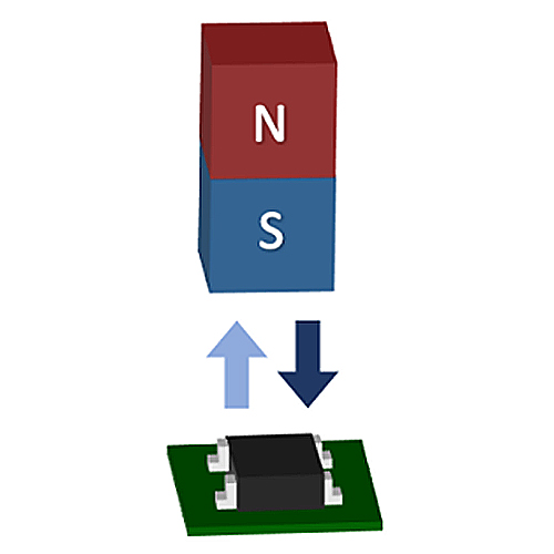
The output voltage is proportional to the magnitude of the magnetic field vertically applied to the sensor and will output positive and negative voltages according to the direction of the magnetic field. The output voltage when there is no vertical magnetic field is 0 V (*1).
*1 There is an offset voltage even when there is no magnetic field in the actual case.
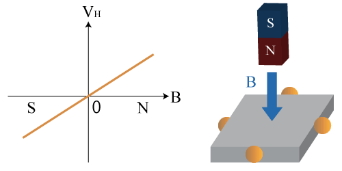 Figure1. Output Characteristic of Hall Element
How to Use
A Hall element has four terminals in total, a control voltage, (or control current), two GND terminals for input, and two differential output terminals. Either constant current drive or constant voltage drive can be supported if it is below the maximum rating.
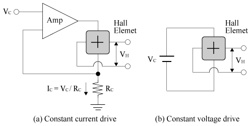 Figure 2. Operation Circuit Diagram (Reference)
Applications
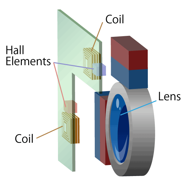
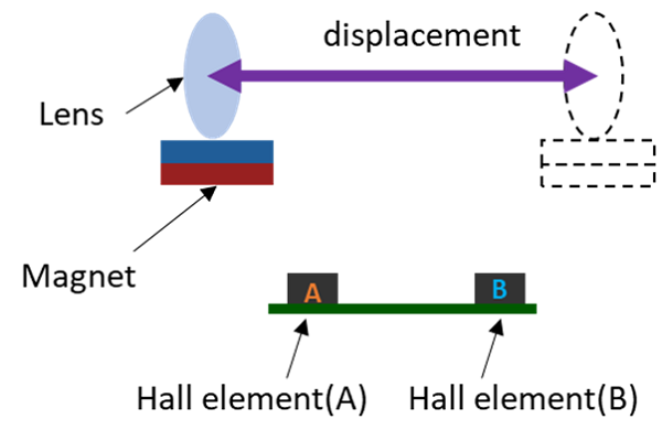
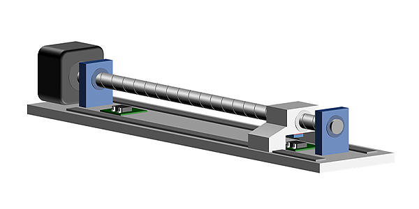
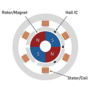
Hall elements are used in brushless DC motors and lens actuators for smart phones and digital still cameras.
Hall IC
Features
A Hall IC compares output of the Hall element with a certain threshold value and outputs it as High or Low. Since the output voltage range is regulated by the power supply, a microcomputer can easily be connected to the subsequent stage. There are switch type that can detect the strength of the magnetic field and latch type that can detect the polarity of the magnetic field.
Output Characteristics
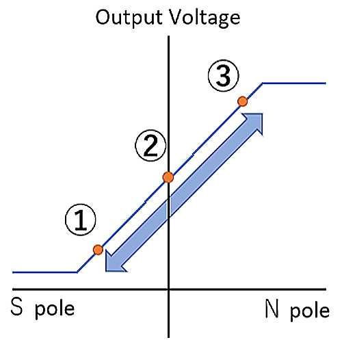
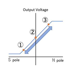
The output voltage is determined to High or Low according to the magnitude of the magnetic field vertically applied to the sensor. There are three kinds of pole detection result: S pole, N pole and bipolar.
When the magnitude of the magnetic field exceeds Bop, the output voltage becomes Low, and when it goes below Brp, the output voltage goes High. In this case, “Brp < Bop (with hysteresis)” is satisfied between Brp and Bop.
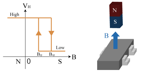 Figure 3. Output Characteristics of Hall IC when South pole is detected
How to Use
A linear Hall IC has two input terminals, that are VCC and GND, and one output terminal. Connecting an IC such as shown in Figure 4 to a Hall element realizes a Hall IC. It is operated by constant voltage driving.
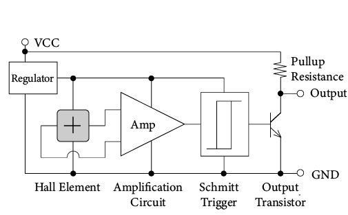 Figure 4. Operation Circuit Diagram (Reference)
Applications
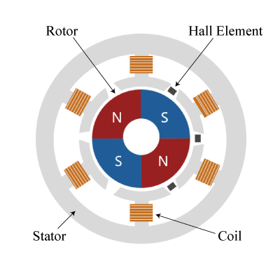
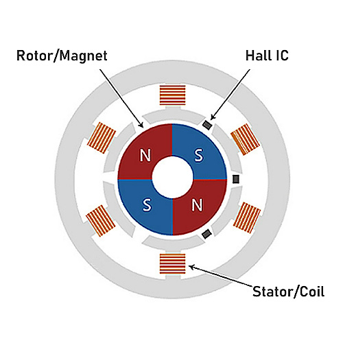
Switch type Hall ICs are used in open/close switches in home electronics and latch type Hall ICs are used in brushless motors or for rotation detection.
Linear Hall IC
Features
A linear Hall IC applies gain to the output of the Hall element resulting in a linear output (*2).
Since the output voltage range is regulated by the power supply, an MCU can easily be connected to the subsequent stage.
*2 Rail-to-Rail output.
Output Characteristics
The output voltage is proportional to the magnitude of the magnetic field vertically applied to the sensor. It ranges from 0V to VCC according to the direction of the magnetic field. The output voltage when there is no vertical magnetic field is VCC/2 (*3).
*3 There is an offset voltage even when there is no magnetic field in the actual case
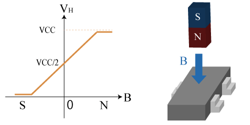 Figure 5. Output Characteristics of Linear Hall IC
How to Use
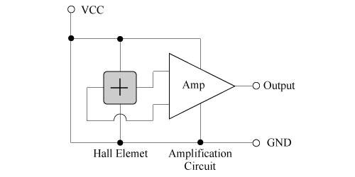
A linear Hall IC has two input terminals, VCC and GND, and one output terminal. Connecting an IC such as shown in Figure 6 to a Hall element realizes a linear Hall IC. It is operated by a constant voltage.
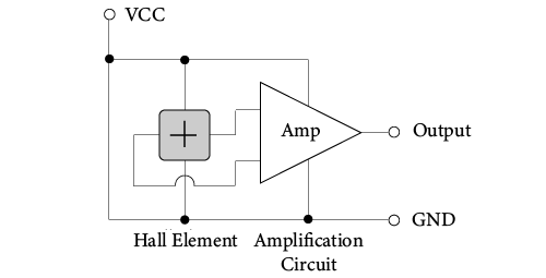 Figure 6. Operation Circuit Diagram (Reference)
Applications
Linear Hall ICs are used in liquid level gauges, current sensors, and angle detection.
What makes AKM different ?
You may be surprised to find AKM's Hall sensors in such products as these! Hall sensors are used in familiar products such as air conditioners, washing machines, and smartphones. Here we will explain why AKM's Hall sensors are widely chosen by many people.
 Hall Sensors
Basic Knowledge of Magnetic Sensor


Basic Knowledge of Magnetic Sensor