-
Products

-
Applications
-
Support
-
About AKM
#04
Principle and advantages of optical encoder
Basic Knowledge of Encoder
This is the fourth part of a series that organizes and introduces the knowledge we have acquired so far. Those who want to study encoders, those who do not deal with encoders but who want to know what the work is. We want to help those people.
In this part, we will introduce the principle and advantages of optical encoder.
Summary
- Optical encoder detects the the optical pulse signals that have passed through the slit, converts them into electrical signals, and outputs them.
- Optical encoder is easier to improve accuracy and resolution than magnetic encoder, and can be used in applications where a strong magnetic field is generated.
- Reflective optical encoder can be easily miniaturized and thinned. Additionally, the assembly process can be simplified because the encoder is manufactured by a stacking method.
4-1. Structure of optical encoder
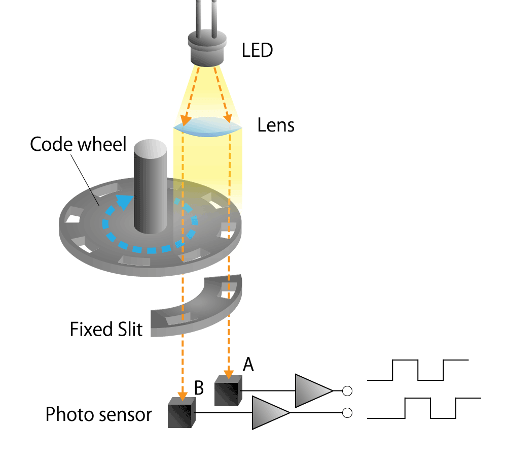
The optical encoder is composed of a light emitting device (LED), photo sensors, and a disc called a code wheel with slits (holes) in the radial direction, and detects rotational position information as an optical pulse signal.
When a code wheel attached to a rotating shaft such as a motor rotates, an optical pulse is generated depending on whether light emitted from a fixed light emitting element passes through a slit of the code wheel or not.
Photo sensor detects the optical pulse, converts it into an electrical signal, and outputs it.
 Figure 4-1. Optical encoder diagram
Light emitting device (LED)
Light emitting devices used in optical encoders are generally inexpensive infrared LEDs, but colored LEDs with shorter wavelengths are sometimes used to suppress light diffusion.
In addition, expensive laser diodes are used in applications that require high performance and high resolution.
Lens
The light emitted from the LED is diffused light with little directivity, so that it is made parallel by using a convex lens.
Code wheel ( movable slit )
The code wheel is a disc with slits ( holes ) for passing/blocking the light emitted from the LED.
The material of the code wheel is metal, resin and glass. Metal is strong robustness against vibration and temperature and humidity and is used in the industrial field.
Resin is cheap and suitable for mass production and used for consumer applications.
Glass is used in applications where high precision and high resolution are required. In addition, a fixed slit may be placed at the position facing the code wheel in order to clarify the passing / blocking of the light that passes through the code wheel and enters the light receiving element.
Photo sensor
Photo sensor is typically photodiode or phototransistor made of semiconductor material such as silicon ( Si ), germanium ( Ge ), and indium gallium phosphide ( InGaP ).
4-2. Principle of optical encoder
Classification by structure
Optical encoders are classified into two types according to their structure.
They are, "transmissive type" in which the light emitting device (LED) and photo sensor sandwich the code wheel, and "reflective type" in which the LED and photo sensor are placed on the same side and the code wheel reflects the light.
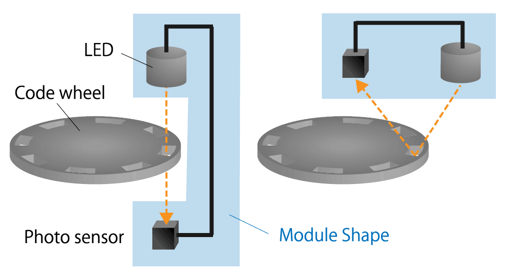 Figure 4-2-1. Optical encoder diagram , Transmissive ( left ) and reflective ( right )
Transmissive type
The photo sensor detects whether the light emitted from the LED passes through the slit of the code wheel or not.
The advantages are:
- Easy to improve signal accuracy
- Easy development due to relatively simple optical path
Reflective type
The photo sensor detects whether the light emitted from the LED is reflected by the code wheel or not.
The advantages are:
- Easy to miniaturize and thin
- Since it can be manufactured by the stacking method, the assembly process can be simplified.
Classification by output electrical signal format
Optical encoders are classified into two types depending on the format of the output electrical signal.
There is an incremental method that outputs the angle change (movement amount) of the rotating disc and an absolute method that outputs the absolute angle of the rotating disc.
The incremental method and the absolute method were explained in detail in part 3.
Higher resolution and higher accuracy
The resolution of an optical encoder is basically determined by the number of slits in the code wheel. Therefore, it is necessary to increase the number of slits in the code wheel in order to achieve high resolution, but it is necessary to reduce the area of each slit in order to be compatible with the miniaturization of the encoder.
As a result, high precision is required for assembling the components, and physical limits are reached somewhere.
In order to further improve the resolution, there is a method of "electrical interpolation" the A phase and B phase of the output signal by using a pseudo sine wave signal instead of a pulse signal.
In this way, the optical encoder can realize high resolution and high accuracy by optimizing the structure of LED, code wheel, photo sensor, etc. and reducing the distortion of the pseudo sine wave.
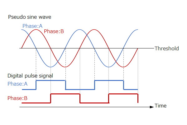 Figure 4-2-2. Pseudo sine wave signal (top) , pulse signal (bottom)
4-3. Advantages and applications of optical encoder
The optical encoder has the advantage that it is easy to improve accuracy and resolution by devising the shape of the slit becasue it has a mechanism that detects whether light passes through the slit or not.
Therefore, it is used for servo control and hollow through shaft type motor control that require high precision.
In addition, since it is not affected by the surrounding magnetic field, it can be used in applications where a strong magnetic field is generated.
Therefore, it is used in devices that use large-diameter motors.
Summary
- Optical encoder detects the the optical pulse signals that have passed through the slit, converts them into electrical signals, and outputs them.
- Optical encoder is easier to improve accuracy and resolution than magnetic encoder, and can be used in applications where a strong magnetic field is generated.
- Reflective optical encoder can be easily miniaturized and thinned. Additionally, the assembly process can be simplified because the encoder is manufactured by a stacking method.
How was it?
In this part, we introduced the principle and advantages of optical encoder. I hope you understand the principle and advantages, and the applications in which optical encoders are used.
In the next part, we will explain the principle and advantages of the magnetic encoder.