-
Products

-
Applications
-
Support
-
About AKM
Glossary of Angle Detection
Rotation Angle Sensors
AKM Angle Sensors Definition of Technical Terms
This page explains commonly used terms in the technical information for AKM's angle sensors.
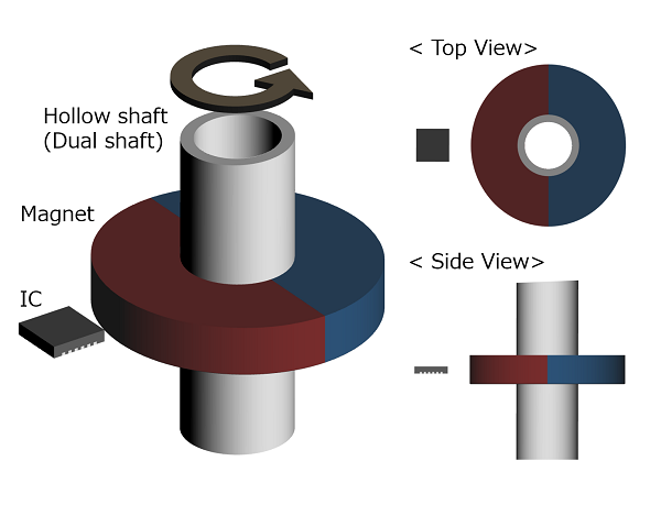
An Off-Axis is a configuration where the sensor center is not located on the rotational axis as shown in the figure. This configuration enables the end of shaft to be used freely, so that it is available for dual shaft motors and hollow shaft motors.
The AK7455 supports Off-Axis configuration.
A shaft-end configuration is where the magnet center and sensor center are aligned on the axis of rotation as shown below.
* Bz=0 if there is no misalignment in the Shaft-End
This is the element that actually detects the magnetic field within the IC package. The position of the sensor element will differ for each product.
Please refer to the datasheet for each product for details on sensor element position.
In the Magnet Selection Guideline, the sensing element is also referred to simply as "sensor".
 Sensor (Sensing element)
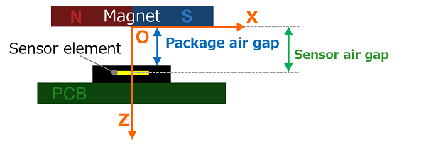
The sensor air gap is defined as the distance between the magnet surface and the sensor element. The package air gap is defined as the distance between the magnet surface and IC package surface. Since the distance from the IC package surface to the sensor element position is different for each product, the package air gap used in the explanation for each product is sometimes referred to simply as "the gap."
In the Magnet Selection Guideline, (a technical document about the AK7455 of rotation angle sensors), the sensor air gap is also referred to simply as "the gap".
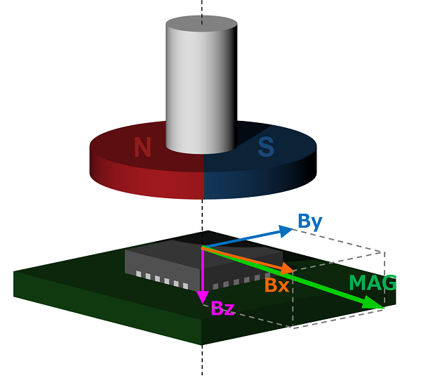
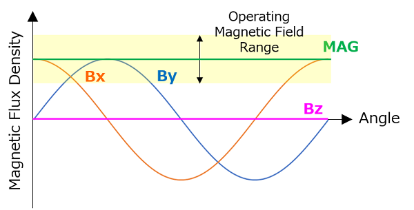
Bx and By are the magnetic field components detected by the AK74xx, which are parallel to the surface of the IC.
* Bz=0 if there is no misalignment in the Shaft-End
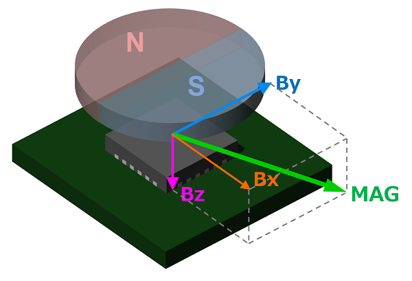 Magnetic Field (Bx, By)
MAG is defined as MAG = √ (Bx2+By2 +Bz2)
The magnetic flux density range needed to detect the rotation angle is called the operating magnetic field range. The operating magnetic field range of the AK7455 is from 30 to 70 mT for a shaft-end configuration. If there is no mounting misalignment in the shaft-end configuration, MAG becomes a constant value.
To account for the variation in mounting tolerances and ambient temperatures, it is recommended to install the sensor in a position where MAG is 50mT when there is no mounting misalignment.
 MAG and Operating Magnetic Field Range
Ideally, the centers of the magnet and the sensor should be aligned on the rotational axis in the shaft-end configuration. Misalignment is defined the distance from the sensor's center to the axis of rotation.
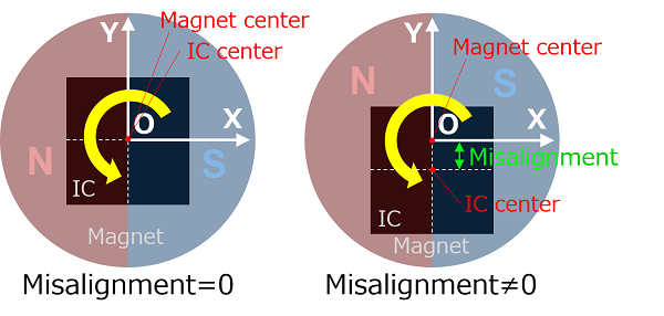 Misalignment (mounting misalignment)
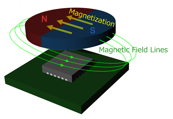
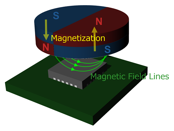
There are two types of magnetization directions: diametral and axial.
A diametral magnet is magnetized across the circumference of the circular face of the magnet, as shown in the lower left figure. An axial magnet is magnetized in the direction perpendicular to the circular face of the magnet as shown in the lower right figure.
AKM's rotation angle sensor detects (transverse) magnetic fields that are oriented parallel to the chip surface. Because of this, the rotation angle sensor is generally used with a diametral dipole magnet.
 Diametral Magnet
 Axial Magnet
A sintered magnet is manufactured by pressing magnetic powders into a specific shape and then cured with intense heat. Sintered magnets typically include ferrite magnets, samarium cobalt magnets and neodymium magnets. These magnets can be found in standard shapes such as a cylinder and a rectangular solid.
Permanent magnets can largely be classified into two types of ferrite magnets : samarium cobalt (SmCo) and neodymium iron boron (NdFeB) . In Magnet Selection Guideline, sintered neodymium magnets and sintered ferrite magnets are introduced as magnets to be used in conjunction with the AK7455.
Ferrite magnets are characterized by low cost and high productivity. Neodymium magnets are more expensive than ferrite magnets, but they offer higher performance with a high residual magnetic flux density.
A sensor is an element or electronic component that detects changes in nature. Typical sensors include switches, potentiometers and encoders that detect position, thermistors that detect temperature, photodiodes that detect light, and piezoelectric elements that detect pressure.
There are analog and digital sensors. In the analog type, impedance (resistance, capacitance, inductance), voltage, and current change continuously according to the physical quantity to be detected. The digital type changes with two values of voltage ON / OFF like a switch and high / low voltage like an encoder.
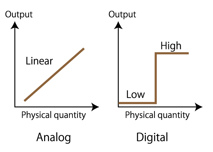 Figure 2. Analog type and digital type
A controller is a control device that judges and processes based on signals from switches and sensors, and has a function to control the movement of actuators. Control by a controller composed of electrical and electronic circuits is called hardware control, and control by a computer program is called software control.
PLCs (Programmable Logic Controllers) have various electric and electronic circuits built in, and can be controlled in various sequences by changing programs, and are used in production facilities such as factories.
Sequence control: Control that performs a series of fixed operations in order.
Actuators are devices that convert various types of energy into mechanical movements such as rotational movement and linear movement.
Typical actuators include motors and sliders.Devices that include a mechanism for rotating or linearly moving using a motor or slider as a power source are called actuators, too. Actuator power sources include hydraulic / pneumatic technology that uses the pressure energy of oil and air, and motors that use electrical energy.
A rotating motor uses an encoder to control the rotation speed and rotation angle, and is used to move machines with high accuracy and speed. With hydraulic pressure, accurate position and speed can be controlled, but it takes time to start moving, so control using an encoder is not used.
Pneumatic pressure does not accurately control position and speed, but is used for automation and labor-saving technologies in factories, etc., by combining simple movements such as forward and backward.
A stepper motor is composed of a magnet attached to a rotating shaft and a fixed coil. It is magnetized by passing a pulse current through the coil and rotates by attracting the rotating shaft magnet.
When the stepper motor rotates faster, the torque (force to rotate the motor) decreases, and the motor cannot follow the pulse speed. This phenomenon is called step-out.
In addition, the phenomenon that the motor rotates unintentionally for some reason when the motor is not rotating is also called step-out.