-
제품

-
애플리케이션
-
서포트
-
AKM 소개
#07
Off-Axis configuration magnetic encoder
Basic Knowledge of Encoder
This is the seventh part of a series that organizes and introduces the knowledge we have acquired so far.
Those who want to study encoders, those who do not deal with encoders but who want to know what the work is. We want to help those people.
In the seventh part, we introduced the angular error of magnetic encoder. In this part, we will explain the Off-Axis configuration magnetic encoder.
Summary
- The advantage of the Off-Axis configuration is that both ends of the rotary shaft can be freed, the encoder as a whole can be made thinner, and hollow through shafts can be supported.
- The Off-Axis configuration magnetic encoder needs correction to make the Lissajous figure a perfect circle, because the Lissajous figure becomes a distorted ellipse.
- For correction, true angle information is necessary to know how much the rotation angle θ includes angular error.
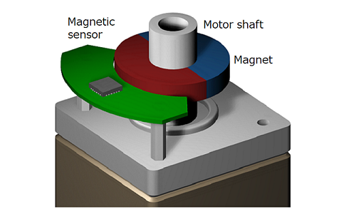 Figure 7-1. Off-Axis configuration magnetic encoder
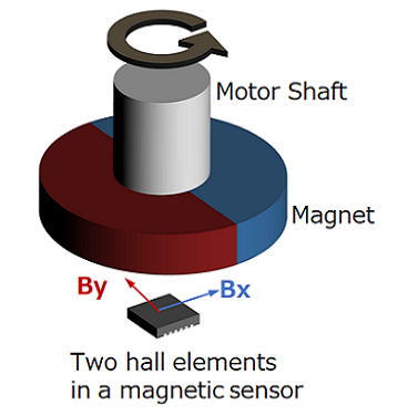
In Part 5 Principles and Advantages of Magnetic Encoders, I explained that the Shaft-End configuration, in which the center of the rotating shaft, the permanent magnet, and the Hall element are aligned, is the ideal configuration for magnetic encoders.
This is because, theoretically, the Lissajous figure becomes a perfect circle and the angular error becomes zero. Therefore, it has a mechanical disadvantage that the tip of the rotating shaft cannot be used for other purposes.
To solve this problem, there is a method in which the tip of the rotary shaft is free by using a configuration in which the encoder is intentionally displaced from the center of the rotary shaft. This method is called Off-Axis configuration.
7-1. Structure of Off-Axis configuration magnetic encoder
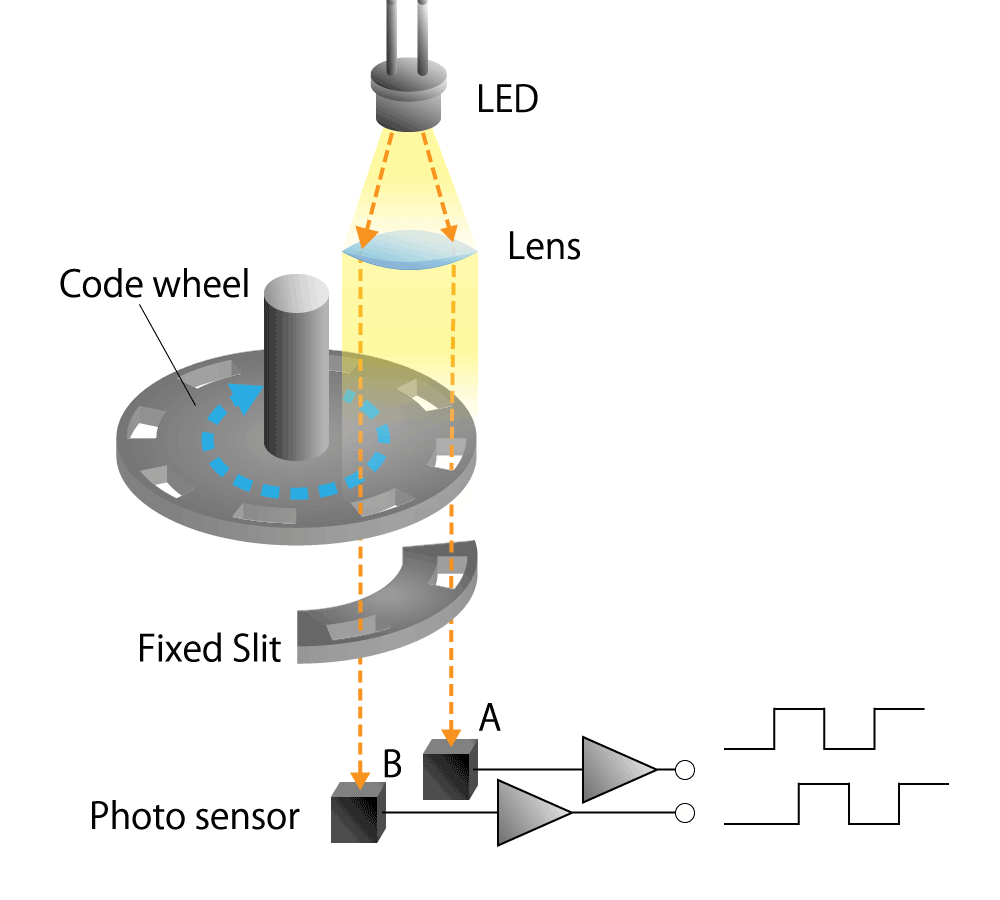
In the following, we will explain in detail the principle until the change of the magnetic field distribution is converted into angular information in the Off-Axis configuration using a magnetic encoder consisting of a magnetic sensor called a Hall element and a permanent magnet.
The Hall element is a magnetic sensor that uses the phenomenon of the Hall effect to output a voltage proportional to the strength of the magnetic field.
(For a detailed explanation of the Hall element, please refer to "Basic knowledge of magnetic sensors" if you are interested.)
Hall element
As introduced in Part 5, Hall elements used in magnetic encoders are made of semiconductor materials such as indium antimony (InSb), gallium arsenide (GaAs), indium arsenide (InAs), and silicon (Si). There are two types of Hall elements that can detect the strength of the magnetic field in the vertical direction and the type that can detect the strength of the magnetic field in the horizontal direction.
Off-Axis magnetic encoders use Hall elements that can detect horizontal magnetic fields.
Permanent magnet
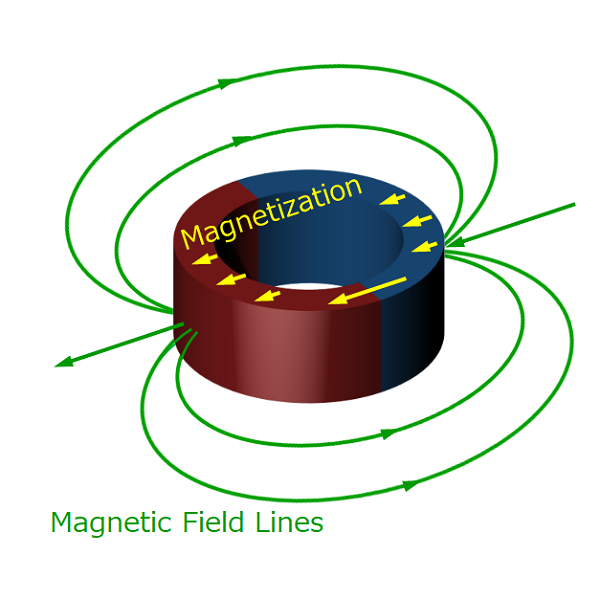 Figure 7-2 . Ring - shaped radially magnetized permanent magnet
Off-Axis magnetic encoders typically use ring-shaped permanent magnets. There are two types of magnetizing directions for permanent magnets: radial direction and plane direction (or axial direction).
In the following, we will explain using the radial type. You can freely select the magnet material and dimensions as long as the magnetic flux density required to operate as an encoder is satisfied. Usually, samarium cobalt (SmCo), which has good temperature characteristics, neodymium (Ne-Fe-B), which is suitable for small size and light weight, and inexpensive ferrite magnet are selected according to the purpose.
Configuration of permanent magnets and Hall elements
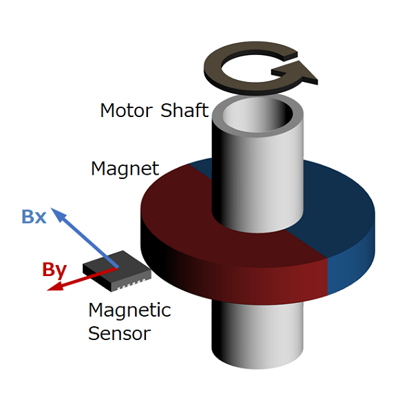
The structure is such that the rotary shaft penetrates through the hole of the ring-shaped permanent magnet.
The Off-Axis configuration is a structure in which the Hall element is intentionally displaced from the center of the rotation axis.
Below, we describe the Off-Axis configuration with an example of placing a Hall element next to a ring magnet to detect the strength of the horizontal magnetic field.
The mechanical advantage of the Off-Axis configuration is that the tip of the rotating shaft can be freed. Another advantage is that the encoder can be made thinner, and a hollow shaft can be used as a rotary shaft to pass cutting oil and cables inside to save space.
 Figure 7-3. Off-Axis magnetic encoder
7-2. Principle of Off-Axis configuration magnetic encoder
Change in magnetic field distribution due to rotational motion
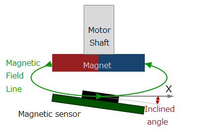
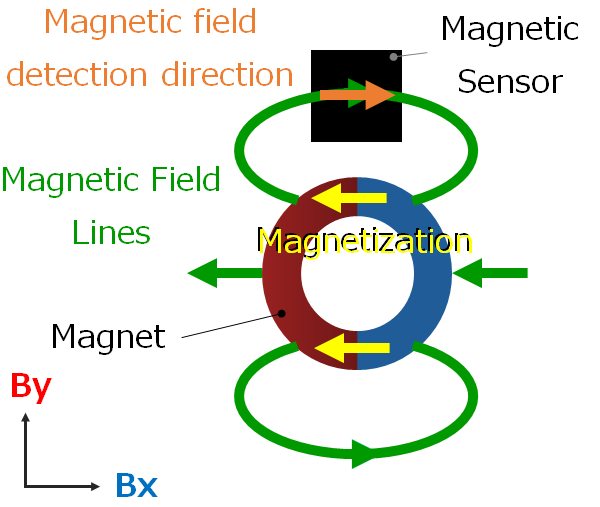
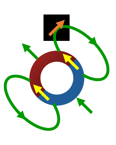
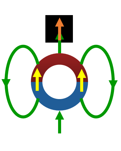
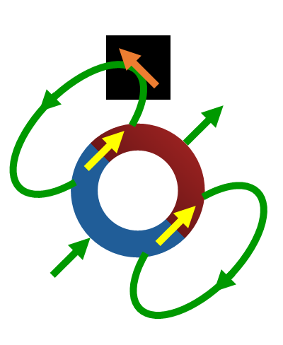
When the motor shaft rotates, the magnetic field created by the ring magnet rotates. A Hall element placed next to the ring magnet receives a magnetic field whose strength and direction change simultaneously.
In the Shaft-End configuration, the rotational direction of the magnet is the same as that of the magnetic field, but in the Off-Axis configuration, the rotational direction of the magnet and the rotational direction of the magnetic field input to the Hall element are opposite. This is similar to the behavior of two meshing gears rotating in opposite directions.
The Hall element detects this change in magnetic field distribution and converts it into an electrical signal. The Hall element is a magnetic sensor that can only detect the strength of a magnetic field in a single direction. Therefore, in order to detect the rotational position, Hall elements are required to detect the magnetic field strengths of the X-axis component and the Y-axis component of the rotating surface.
 θ = 0°
 θ = 45°
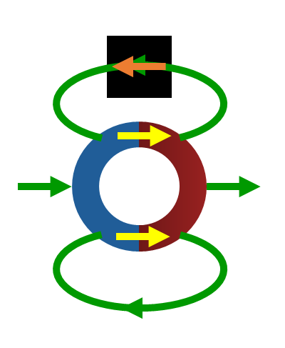
 θ = 90°
 θ = 135°
 θ = 180°
Figure 7-4. Magnetic field input to Hall element in Off-Axis configuration
Converting electric signal of Hall element into angle information
The AD converter converts the magnetic field information of the X-axis component and Y-axis component converted into electrical signals by the Hall element into digital signals. The digital signal is sent to the arithmetic circuit and converted into angle information using trigonometric functions. A plane figure obtained by synthesizing the X-axis component and the Y-axis component orthogonal to each other is called a Lissajous figure (or Lissajous waveform). The Lissajous figure with Off-Axis configuration becomes a considerably distorted ellipse.
There are two reasons. One is that the magnetic field strength and direction of the ring magnet rotate while changing simultaneously, and the other is that the rotation angle of the ring magnet does not match the direction of the magnetic field input to the Hall element. When the X-axis component is Bx and the Y-axis component is By, the rotation angle θ can be obtained as an absolute angle by the calculation of arctan(By/Bx). Since the Lissajous figure with Off-Axis configuration is distorted, the rotation angle θ contains a large angle error.
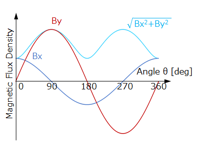 Figure 7-5a. Off-Axis configuration X-axis magnetic field Bx and Y-axis magnetic field By
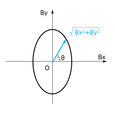 Figure 7-5b. Off-Axis configured Lissajous figure
Correcting the angle information of the Hall element
The Off-Axis configuration is sure to correct for removing angular errors contained in the rotation angle θ. There are two typical correction methods. One is to make a table of the rotation angle θ and the true angle in advance, and perform linear interpolation while referring to the table information.
The other is a method of canceling the angular error by calculating the correction parameter from the information of the error component included in the rotation angle θ in advance and correcting it so that the Lissajous figure becomes a perfect circle. Both methods have something in common. This means that calibration requires reference angle information to know how much angular error is included in the rotation angle θ. Usually, the angle information of another configured encoder or the pointing angle information of the stepping motor is used as a reference.
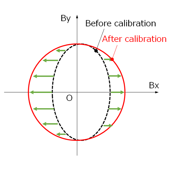 Figure 7-6. Correct so that the Lissajous figure becomes a perfect circle
7-3. Advantages and applications of Off-Axis configuration magnetic encoder
The magnetic encoder has an excellent advantage of being robust in an environment contaminated with dust, oil, water and so on because it has a mechanism to detect changes in the magnetic field. Thus, it is suitable for use in the environment with a lot of dust, oil, and water.
Furthermore, the mechanical advantage of the Off-Axis configuration is that the tip of the rotating shaft can be freed.
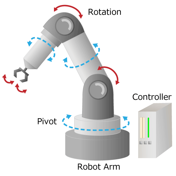
Therefore, it is used in main motors of industrial sewing machines and motors with electromagnetic brakes. It is also suitable for applications where the rotating shaft is a hollow shaft and cutting oil and cables are passed inside. It is used in machine tool spindle motors and robot arms.
Summary
- The advantage of the Off-Axis configuration is that both ends of the rotary shaft can be freed, the encoder as a whole can be made thinner, and hollow through shafts can be supported.
- The Off-Axis configuration magnetic encoder needs correction to make the Lissajous figure a perfect circle, because the Lissajous figure becomes a distorted ellipse.
- For correction, true angle information is necessary to know how much the rotation angle θ includes angular error.
How was it?
In this part, we introduced the Off-Axis configuration magnetic encoder. I hope you understand the principle and advantages, and the applications in which Off-Axis configuration magnetic encoders are used.
Column 2. Visualization of stray magnetic field
The magnetic encoder with Shaft-End configuration has zero angular error when the Lissajous figure is a perfect circle. In the Off-Axis configuration, the angular accuracy is improved by correcting the Lissajous figure so that it becomes a perfect circle. In contrast, as explained in Part 6, if the Lissajous figure is no longer a perfect circle due to the influence of a stray magnetic field, an angular error will occur.
Since the magnetic encoder has such properties, it is possible to determine whether the input magnetic field of the encoder is normal or abnormal by monitoring the amount of variation of the Lissajous figure from a perfect circle. In other words, it is visualization of the stray magnetic field.
For example, a program that issues an alarm when the amount of variation in the Lissajous figure exceeds a certain threshold can be used as predictive maintenance of the system.
Basic Knowledge of Encoder