-
제품

-
애플리케이션
-
서포트
-
AKM 소개
#06
Angular error of magnetic encoder
Basic Knowledge of Encoder
This is the sixth part of a series that organizes and introduces the knowledge we have acquired so far.
Those who want to study encoders, those who do not deal with encoders but who want to know what the work is. We want to help those people.
In the sixth part, we introduced the principle and advantages of magnetic encoder. In this part, we will explain the angular error of the magnetic encoder.
Summary
- By keeping objects that generate a magnetic stray field or objects that easily transmit magnetism away from the magnetic encoder, the distortion of the magnetic field input to the Hall element is prevented and the angular error is reduced.
- By increasing the magnetic field input to the Hall element, the angular error due to electrical noise is reduced.
- The rotation angle sensor IC, which incorporates the Hall element, AD converter, and arithmetic circuit required for the magnetic encoder, has small sensitivity deviation and offset, reduces errors due to temperature fluctuations, and has a self-alignment effect that prevents mounting misalignment.
6-1. Why does the angular error of the magnetic encoder occur?
In the Shaft-End configuration in which the center of the rotation axis, the permanent magnet, and the center of the Hall element are aligned on the same line, the Lissajous figure is theoretically a perfect circle and the angular error is zero. However, in reality, the Lissajous figure is no longer a perfect circle for some reasons, which causes an angular error. We will introduce the typical causes of angular error.
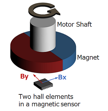
In the following, we will explain the operating principle of the Off-Axis configuration using a magnetic encoder consisting of a magnet magnetized in the radial direction and a Hall element that detects the strength of the horizontal magnetic field.
Stray magnetic field
An angular error occurs due to the influence of the stray magnetic field input from the horizontal direction of the permanent magnet.
For example, if a stray magnetic field is input in the X-axis direction, the center of the Lissajous figure will be offset in the X-axis direction. At this time, the angular error is zero when the rotation angle θ is 0° and 180°, but the angular error occurs in other cases.
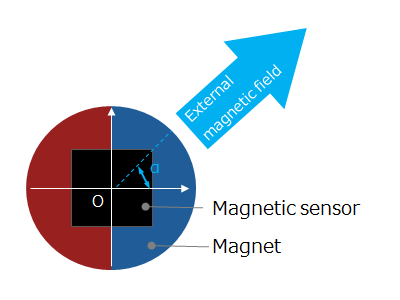 Figure 6-1a. A stray magnetic field is input in the horizontal direction
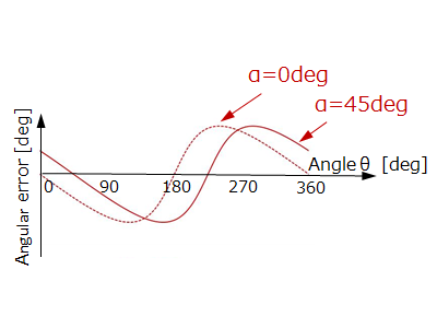 Figure 6-1b. Angular error when a stray magnetic field is input in the X-axis direction
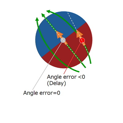
Figure 6-1c shows the Lissajous figure and angular error when a stray magnetic field is input in the X-axis direction (α=0°). The angular error is zero when the rotation angle θ is 0° and 180°, but the phase is delayed between 0 and 180°, and the phase is advanced between 180° and 360°.
 Figure 6-1c. Lissajous figure and angular error when a stray magnetic field is input from the X-axis direction
Figure 6-1d shows the Lissajous figure and angular error when input from the α=45° direction. The angular error is zero when the rotation angle θ is 45° and 225°, but the phase is delayed between 45 and 225°, and the phase is advanced between 225° and 45°
 Figure 6-1d. Lissajous figure and angular error when a stray magnetic field is input from the 45° direction
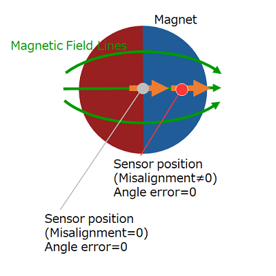
Mounting misalignment of Hall element
An angular error occurs due to mounting misalignment of the Hall element. This is because the magnetic field input to the Hall element is distorted due to the centers of the Hall element and the permanent magnet being displaced.
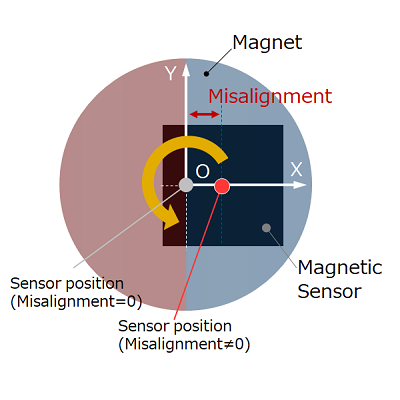 Figure 6-2a. misalignment of Hall element
For example, if the Hall element is misaligned in the X-axis direction, the angular error is 0 when the rotation angle θ is 0°, 90°, 180°, or 270°.
However, the phase advances between 0~90° and 180~270°, and the phase lags between 90~180° and 270~0°.
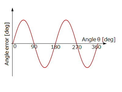 Figure 6-2b. Angular error when misaligned in the X-axis direction
 θ = 0°
 θ = 45°
 θ = 90°
 θ = 135°
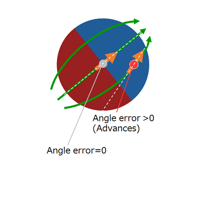
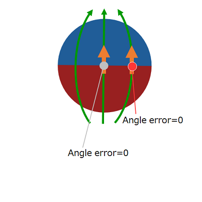
Figure 6-2c. Magnetic field input to the Hall element when misaligned in the X-axis direction
(θ=0°、45°、90°、135°)
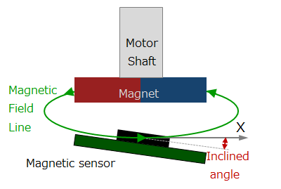
Mounting inclination of Hall element
An angular error occurs due to the mounting inclination of the Hall element. The Hall element and the permanent magnet are not offset from each other, but the Lissajous figure becomes an ellipse because the magnetic field input from the inclined direction becomes weak. For example, when the Hall element is tilted with respect to the X-axis direction, the magnetic field input to the Hall element becomes weaker when the rotation angle θ is 0° and 180°. Whereas, at 90° and 270°, the magnetic field strength is not affected by the tilt. As a result, the Lissajous figure becomes an ellipse with a small radius in the X direction. In this case, the angular error is 0 when the rotation angle θ is 0°, 90°, 180°, and 270°. However, the phase advances between 0~90° and 180~270°, and the phase lags between 90~180° and 270~0°.
 Figure 6-3a. mounting inclination of the Hall element
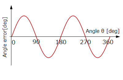 Figure 6-3b. Angular error when tilted in the X-axis direction
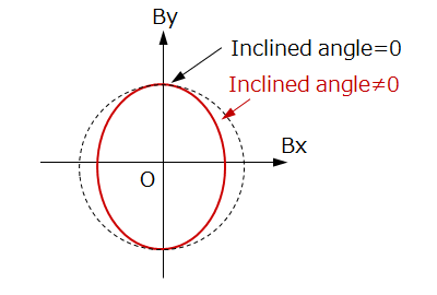 Figure 6-3c. Lissajous figure when tilted in the X-axis direction
In contrast, if the Hall element is mounted in the correct position, no angular error will occur even if the permanent magnet is misaligned or tilted. This is because the magnitude of the magnetic field input to the Hall element does not change depending on the angle even if the magnet rotates with misalignment. As a result, the Lissajous figure remains a perfect circle and no angular error occurs.
However, the magnitude of the horizontal magnetic field detected by the magnetic sensor becomes small, so the noise error component included in the angle information becomes relatively large.
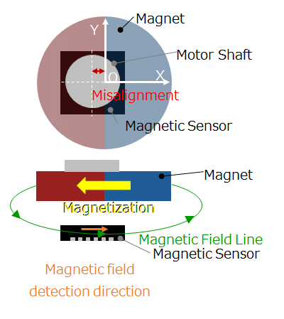 Figure 6-4a. misalignment of permanent magnet
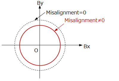 Figure 6-4b. Lissajous figure when the permanent magnet is misaligned in the X-axis direction
Characteristic deviation of magnetic sensor and electronic components
The Hall element and AD converter that make up the magnetic encoder are electronic components. Electronic characteristics of mass-produced electronic parts have individual differences due to production deviations.
For example, the offset of the Hall element causes an angular error for the same reason as the effect of the stray magnetic field. The difference between the sensitivity of the Hall element for detecting the magnetic field of the X-axis component and the sensitivity of the Hall element for detecting the magnetic field of the Y-axis component causes an angular error for the same reason as the mounting inclination of the Hall element. Similarly, the offset and sensitivity deviation of the AD converter also cause the angular error.
6-2. How to reduce the angular error of the magnetic encoder?
In the Shaft-End configuration, the angular error is zero when the Lissajous figure is a perfect circle. However, it is an ideal condition in which there is no stray magnetic field, there is no misalignment of Hall element, mounting tilt, and there is no offset or sensitivity deviation of electronic components.
In reality, such an ideal encoder cannot be mass-produced. A robust design is required to reduce the angular error of mass-produced encoders. Robustness refers to an internal mechanism or property that prevents a system from changing due to the effects of external disturbances such as stress and changes in the environment. In other words, it is necessary to design so that an angular error does not easily occur even if there is a stray magnetic field, misalignment, mounting tilt, or characteristic deviation of electronic components.
Shielding stray magnetic field
Keep away from the encoder those that generate magnetism (magnets/electromagnets) and those that easily pass magnetism (magnetic materials). This prevents the magnetic field input to the Hall element from being distorted.
For example, it is very effective to use a non-magnetic material for the rotating shaft of the motor and the jig that fixes the magnet to the rotating shaft. Also, by shielding the surroundings of the encoder with a magnetic material, the effects of stray magnetic fields can be prevented.
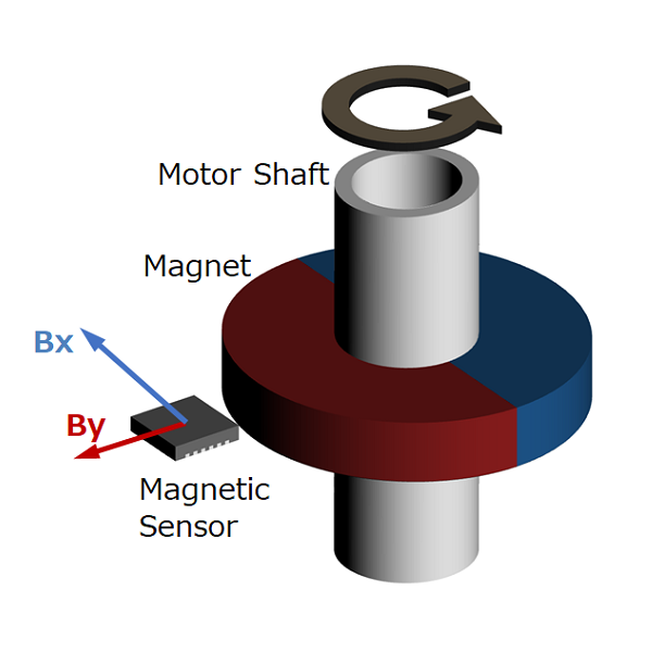
For example, for a Hall element that detects a magnetic field in the horizontal direction, it is very effective to enclose the horizontal direction with a shield. Furthermore, by placing the Hall element in the center of the ring magnet, the ring magnet itself exhibits the same effect as the shield.
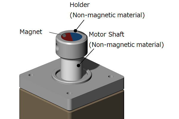 Figure 6-5a. Motor rotation axis and magnet
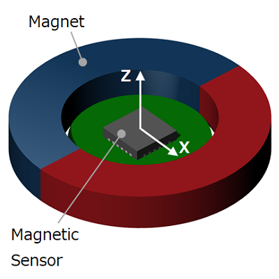 Figure 6-5b. Hall element placed in the center of the ring magnet
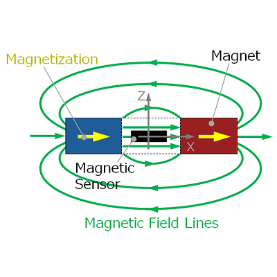 Figure 6-5c. Magnetic field distribution when the Hall element is placed in the center of the ring magnet
Reducing the impact of mounting misalignment
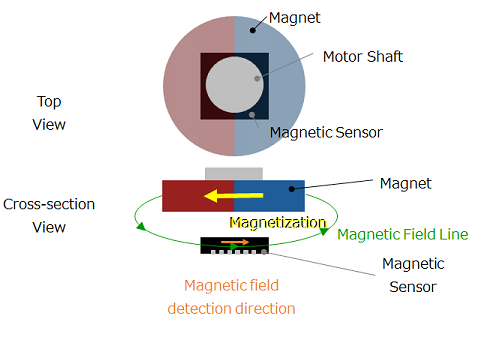 Figure 6-6a. A combination of a radially magnetized magnet and a Hall element that detects the strength of the horiontal magnetic field
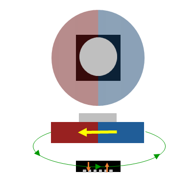 Figure 6-6b. A combination of a radially magnetized magnet and a Hall element that detects the strength of the vertical magnetic field
As mentioned in the principle and advantages of the magnetic encoder in Part 5, the combination of the Hall element that detects the horizontal magnetic field and the magnet magnetized in the radial direction reduces the angular error due to misalignment.
Strengthening the magnetic field input to the Hall element
The output signal of the Hall element increases in proportion to the strength of the input magnetic field. In contrast, the Hall element has a certain amount of noise component regardless of the strength of the magnetic field because it is an electrically resistive element.
Therefore, by increasing the magnetic field input to the Hall element, the signal component/noise component ratio increases and the angular error caused by noise can be reduced.
Using a rotation angle sensor with all integrated electronic components
The rotation angle sensor IC has Hall elements and AD converters for X axis and Y axis on the same silicon (Si) chip. Therefore, the sensitivity deviation is smaller than that of combining discrete parts, and the temperature characteristics of sensitivity are also uniform. As a result, the error of the rotation angle θ ( see Part 5 ) obtained by the calculation of arctan(By/Bx) can be reduced. In addition, the Hall element receives stress from the epoxy resin of the package and causes offset temperature fluctuation.
The rotation angle sensor IC can reduce the angular error due to temperature fluctuations by placing a Hall element in the center of the square package and applying as little stress as possible. In addition, placing the terminals on the four sides of the package has a self-alignment effect that prevents misalignment of board mounting.
Summary
- By keeping objects that generate a magnetic stray field or objects that easily transmit magnetism away from the magnetic encoder, the distortion of the magnetic field input to the Hall element is prevented and the anglular error is reduced.
- By increasing the magnetic field input to the Hall element, the anglular error due to electrical noise is reduced.
- The rotation angle sensor IC, which incorporates the Hall element, AD converter, and arithmetic circuit required for the magnetic encoder, has small sensitivity deviation and offset, reduces errors due to temperature fluctuations, and has a self-alignment effect that prevents mounting misalignment.
How was it?
In this part, we introduced the angular error of the magnetic encoder. I hope you understand causes and countermeasures for angular error.
In the next part, we will explain the Off-Axis configuration magnetic encoder.