-
제품

-
애플리케이션
-
서포트
-
AKM 소개
#05
Principle and advantages of magnetic encoder
Basic Knowledge of Encoder
This is the fifth part of a series that organizes and introduces the knowledge we have acquired so far.
Those who want to study encoders, those who do not deal with encoders but who want to know what the work is. We want to help those people.
In this part, we will introduce the principle and advantages of magnetic encoder.
Summary
- Magnetic encoder detects rotational position information as changes of the magnetic field, converts them into electrical signals, and outputs them.
- Magnetic encoder with a Shaft-End configuration that combines a magnet magnetized in the radial direction and a Hall element that detects the strength of the horizontal magnetic field is robust against misalignment.
- Magnetic encoders are used for applications that place importance on robust against environment, small size and lightweight, and high reliability.
- Magnetic encoders are beginning to be used even in the market occupied by optical encoders because their accuracy and resolution are improved and the hollow through shaft can be supported.
5-1. Structure of magnetic encoder
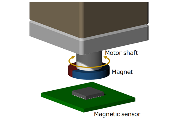 Figure 5-1. Magnetic encoder diagram
The magnetic encoder detects rotational position information as changes of the magnetic field, converts them into electrical signals, and outputs them. The simplest magnetic encoder consists of a permanent magnet and a magnetic sensor. The permanent magnet is attached to the tip of a rotating body such as a motor shaft, and the magnetic sensor is fixed in a state where it is mounted on a PCB board at a position where it receives the magnetic field generated by the permanent magnet. When the permanent magnet attached to the motor shaft rotates, the direction of the magnetic field detected by the magnetic sensor changes, as a result the encoder detects the rotational position and speed of the motor shaft.
In the following, we will explain in detail the principle of operation until the change of the magnetic field distribution is converted into angular information, using a magnetic encoder consisting of a magnetic sensor called a Hall element and a permanent magnet. The Hall element is a magnetic sensor that uses the phenomenon of the Hall effect to output a voltage proportional to the strength of the magnetic field.
Hall element
Hall elements used in magnetic encoders are made of semiconductor materials.
The semiconductor materials used in Hall elements are mainly compound semiconductors such as highly sensitive indium antimony (InSb), gallium arsenide (GaAs) with stable temperature characteristics, and indium arsenide (InAs) with well-balanced sensitivity and temperature characteristics. And silicon (Si) that can be mounted on the IC chip is used, too.
In addition, there are two types of Hall elements that can detect the magnetic field strength in the vertical direction and the type that can detect the magnetic field strength in the horizontal direction.
(For a detailed explanation of the Hall element, please refer to " Basic knowledge of magnetic sensors " if you are interested.)
Permanent magnet
Magnetic encoders generally use cylindrical permanent magnets. There are two types of magnetizing directions for permanent magnets: radial direction and plane direction (or axial direction).
As long as the conditions for the magnetic flux density required to operate as an encoder are satisfied, the magnetic material and dimensions can be freely selected.
Generally, samarium-cobalt (SmCo) - based magnets, which have good temperature characteristics, neodymium (Ne-Fe-B) - based magnets, which are suitable for downsizing and lightweight, and inexpensive ferrite - based magnets are selected according to the purpose.
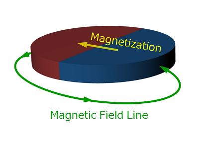 Figure 5-2a. Radially magnetized magnet
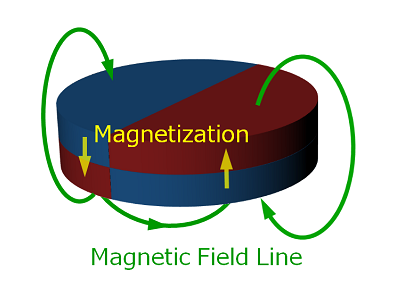 Figure 5-2a. Radially magnetized magnet
Configuration of permanent magnets and Hall elements
The ideal position of the magnetic encoder is that the center of the rotary shaft, the permanent magnet, and the Hall element are aligned on the same line. Such a configuration is called "Shaft-End configuration".
However, even with Shaft-End configuration, there is actually a slight position error called "misalignment". When the Hall element is misaligned, the strength of the magnetic field detected by the Hall element changes, resulting in an error of the angle detection accuracy. It is very difficult to completely eliminate misalignment.
However, in the Shaft-End configuration, the Hall element is placed in the area where the horizontal magnetic field is uniform, so that the effect of misalignment can be reduced if the Hall element detects the strength of the horizontal magnetic field.
Therefore, the Hall element that detects the strength of the horizontal magnetic field can reduce the angular error due to misalignment compared to the Hall element that detects the strength of the vertical magnetic field.
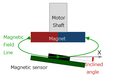
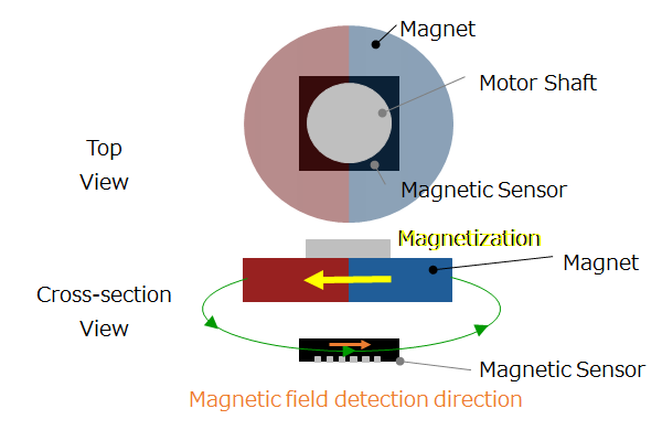 Figure 5-3a. A combination of a radially magnetized magnet and a Hall element that detects the strength of the horizontal magnetic field
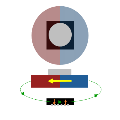 Figure 5-3b. A combination of a radially magnetized magnet and a Hall element that detects the strength of the vertical magnetic field
If you want to reduce the leakage magnetic field because the magnetic field leaking in the side direction adversely affects surrounding equipment, use a permanent magnet magnetized in the plane direction.
However, compared to a magnet magnetized in the radial direction, the area of the uniform magnetic field in the horizontal direction is narrowed, so the angular error due to misalignment is relatively large.
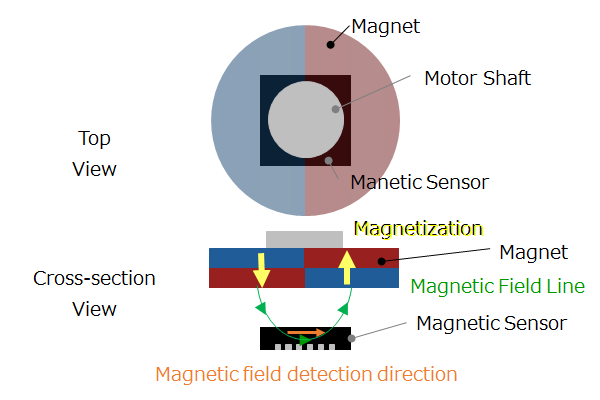 Figure 5-4a. A combination of a magnet magnetized in the plane direction and a Hall element that detects the strength of the horizontal magnetic field
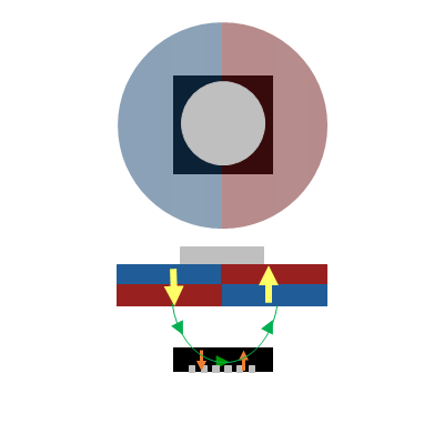 Figure 5-4b. A combination of a magnet magnetized in the plane direction and a Hall element that detects the strength of the vertical magnetic field
In this way, the advantage of the Shaft-End configuration is that it is possible to easily realize an encoder that is robust against misalignment by combining the magnet magnetized in the radial direction and the Hall element that detects the strength of the horizontal magnetic field. Actually, there is also a usage of Off-Axis configuration in which Hall element is placed at a position different from Shaft-End, but that will be explained in detail in the subsequent part.
In the following, we will explain the principle of a magnetic encoder consisting of a magnet magnetized in the radial direction and a Hall element that detects the strength of the horizontal magnetic field.
5-2. Principle of magnetic encoder
Detecting rotational movement as a magnetic field change and converting it into an electrical signal
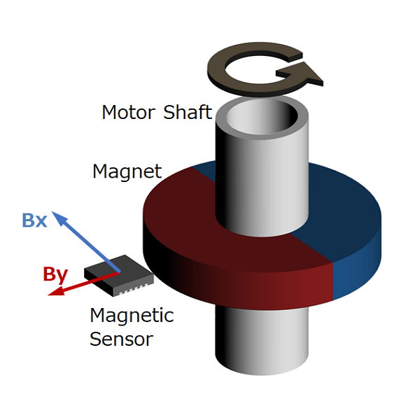
When the motor shaft rotates, the magnetic field created by the permanent magnet attached to the tip of the shaft also rotates. At this time, the magnetic field rotates with constant strength in the area near the center of the rotation axis. The Hall element detects this change of magnetic field distribution and converts it into an electrical signal. The Hall element is a magnetic sensor that can only detect the strength of a magnetic field in a single direction. Therefore, in order to detect the rotational position of the XY rotation plane, a Hall element for detecting the strength of the X axis component (Bx) and a Hall element for detecting the strength of the Y axis component (By) are required.
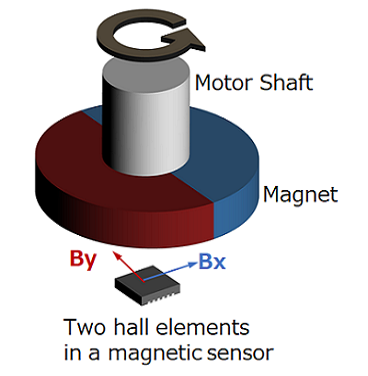 Figure 5-5a. Shaft-End configuration magnetic encoder
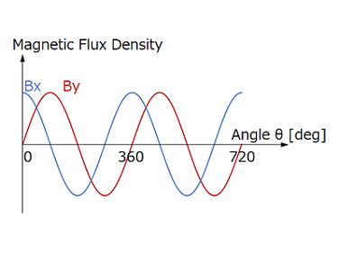 Figure 5-5b. Magnetic field strength detected by Hall element
Converting electric signal of Hall element into angle information
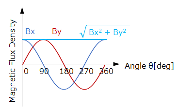 Figure 5-6a. Magnetic field of X-axis component (Bx) and Y-axis component (By)
The magnetic field information of the X-axis component and Y-axis component converted into an electric signal by the hall element is converted into a digital signal by the AD converter. Furthermore, it is sent to an arithmetic circuit and converted into angle information using a trigonometric function. A plane figure obtained by synthesizing the X-axis component and the Y-axis component orthogonal to each other is called a Lissajous figure (or Lissajous waveform). Under the Shaft-End configuration without misalignment, the strength of the rotating magnetic field does not change, so the Lissajous figure draws a perfect circle. Therefore, the angle output result converted by the trigonometric function has zero error. In addition, even if the Hall element that detects the strength of the horizontal magnetic field is misaligned, the magnetic field input to the Hall element does not change much, so the angular error included in the calculation result is small.
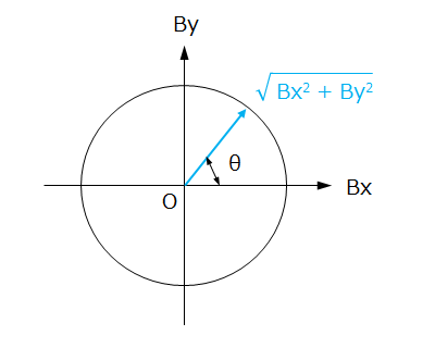 Figure 5-6b. Lissajous figure of magnetic field strength
When the X-axis component is Bx and the Y-axis component is By, the rotation angle θ can be obtained as an absolute angle by calculating arctan(By/Bx). This can be output with the absolute method introduced in Part 3. That is, a magnetic encoder is essentially an absolute angle-sensing encoder. In addition, by converting the absolute angle information into A-phase, B-phase, and Z-phase information, it can be output as a pulse signal in the incremental method/pseudo-absolute method. At this time, if the resolution of absolute angle information is sufficiently high, it is possible to output a pulse signal of any resolution such as 360 ppr, 1000 ppr, 2500 ppr, 4000 ppr.
Rotation angle sensor IC
A rotation angle sensor IC is an electronic component that incorporates all the magnetic sensors, AD converters, and angle calculation circuits that are the necessary components for a magnetic encoder.
It is possible to realize a small magnetic encoder with a very simple structure of a rotation angle sensor IC and a permanent magnet.
It is widely used in consumer, industrial and automotive applications.
5-3. Advantages and applications of magnetic encoder
Since the magnetic encoder has a mechanism to detect changes of the magnetic field, it has an excellent advantage of being robust in an environment contaminated with dust, oil, water, etc. Therefore, it is suitable for use in environments with a lot of dust, oil, and water. For example, magnetic encoders are used in industrial sewing machines used in environments with a lot of lint and machine tools used in environments where cutting oil and water splash.
Another advantage is that it is possible to manufacture an encoder that outputs an absolute angle with a very simple structure of a rotation angle sensor IC and a permanent magnet. Therefore, it is suitable for applications that require small size, light weight, and high reliability. For example, it is used in machine tools that use small-diameter motors and factory automation machines that require durability.
In general, optical encoders are used in applications that require high precision and resolution, and magnetic encoders are used in applications that place importance on environmental robustness, small size, and high reliability. However, since the latest magnetic encoders have improved accuracy and resolution and are compatible with hollow through shafts, magnetic encoders are beginning to be used in the market occupied by optical encoders.
Summary
- Magnetic encoder detects rotational position information as changes of the magnetic field, converts them into electrical signals, and outputs them.
- Magnetic encoder with a Shaft-End configuration that combines a magnet magnetized in the radial direction and a Hall element that detects the strength of the horizontal magnetic field is robust against misalignment.
- Magnetic encoders are used for applications that place importance on robust against environment, small size and lightweight, and high reliability.
- Magnetic encoders are beginning to be used even in the market occupied by optical encoders because their accuracy and resolution are improved and the hollow through shaft can be supported.
How was it?
In this part, we introduced the principle and advantages of magnetic encoder. I hope you understand the principle and advantages, and the applications in which magnetic encoders are used.
In the next part, we will explain the angular error of magnetic encoder.