-
제품

-
애플리케이션
-
서포트
-
AKM 소개
#02
Encoder types and mechanism
Basic Knowledge of Encoder
This is the second part of a series that organizes and introduces the knowledge we have acquired so far.
Those who want to study encoders, those who do not deal with encoders but who want to know what the work is. We want to help those people.
Summary
- An encoder detects the rotation of objects as a physical change amount by the sensor element, and finally transmits rotation/angle information to the outside as an electrical signal.
- An encoder is classified into four types: mechanical, optical, magnetic, and electromagnetic induction types.
- There are four types of information necessary to rotate the motor with high accuracy: rotation amount, rotational speed, rotational direction, and rotational position.
2-1. What is the mechanism for detecting rotation and angle?
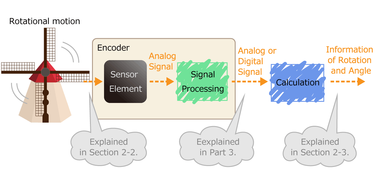 Figure 1. Process of converting rotational motion into rotational information
In the first part, we mentioned that an encoder is a sensor that detects rotation angle, linear displacement, and speed. A sensor is an element or electronic component that detects changes of nature phenomenon. For example, an optical sensor detects on/off of light, and a magnetic sensor detects a magnetic field distribution.
The sensor has the following roles. By outputting the detected physical quantity change as an electrical signal, information can be transmitted to the outside. As shown in Figure 1, the encoder processes the electrical signal output from the sensor element, and finally sends the rotation/angle information to the outside as a digital or analog electrical signal.
2-2. What physical quantity changes when rotating?
The difference in the physical quantity to be measured means the difference in the detection method of the sensor, so it is an essential component that determines the advantages and disadvantages of encoders.
The encoders are classified into the following four types according to the detection method.
Mechanical type (contact type)
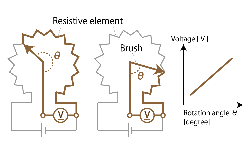 Figure 2. Mechanical (Contact type) encoder diagram
This method detects the rotational position with a variable resistor whose electrical resistance changes in proportion to the rotation angle. Such a mechanical encoder is generally called a potentiometer.
When the slider moves on resistors, the resistance value of the potentiometer changes in proportion to the moving distance of the slider.
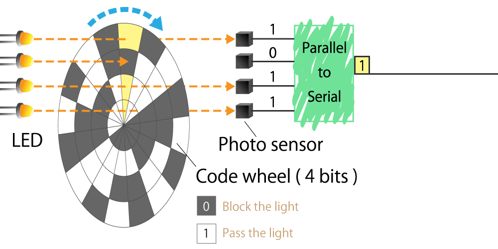
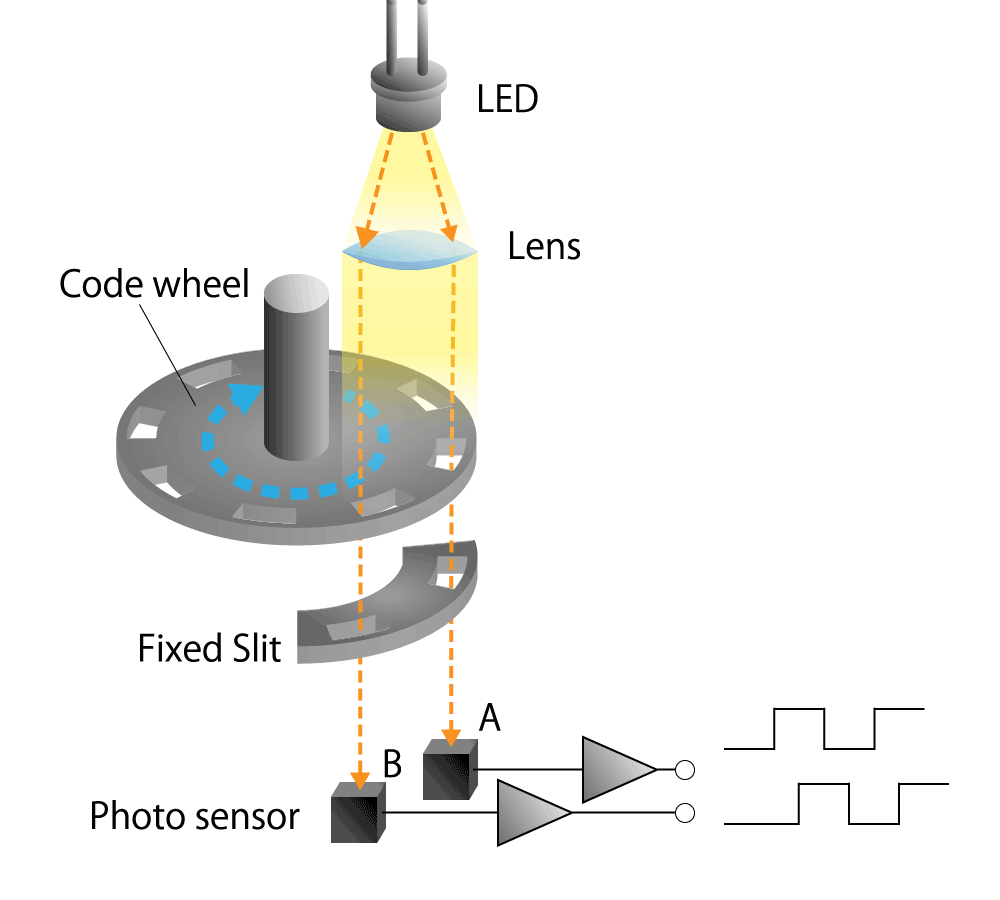
Optical type
This is a method that uses a light sensor to detect whether light passes through a slit in the radial direction of a rotating disk called a code wheel attached to the motor shaft.
The light pulse signal changes as it passes through the slit, and the amount of rotation of the motor shaft can be detected by counting the number of pulses. We will explain the operating principle and features in part 4.
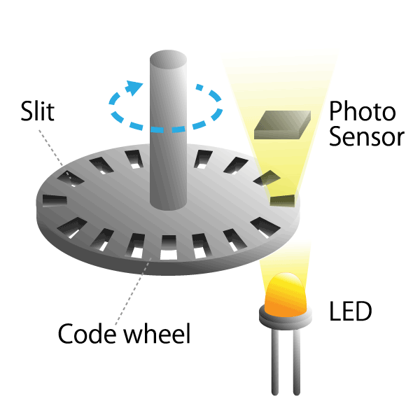 Figure 3. Optical encoder diagram
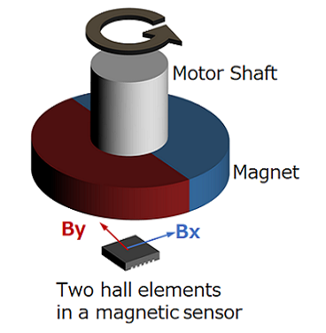
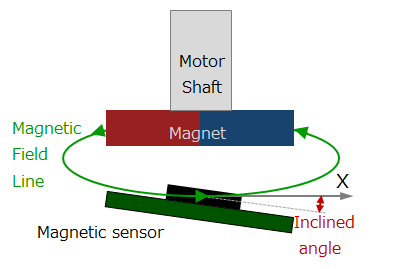
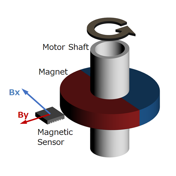
Magnetic type
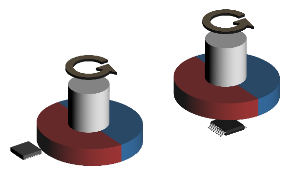 Figure 4. Magnetic encoder diagram
This method uses a magnetic sensor to measure changes in the magnetic field distribution created by a permanent magnet attached to the motor shaft.
When the motor rotates, the magnetic field distribution of the permanent magnet also changes, so if you detect it with a magnetic sensor, you can determine the rotational position of the motor shaft. We will explain the operating principle and features in part 5.
Electromagnetic induction type
This method reads changes in the magnetic field generated between the induction coil (excitation coil) and fixed coil (detection coil) attached to the motor shaft.
The basic principle is the same as a transformer using electromagnetic induction, and such an encoder is called a resolver.
The power supply to the rotating induction coil of the resolver has a risk of wear due to the contact method using a brush. However, there is a VR (Variable Reactance) resolver that improves this risk.
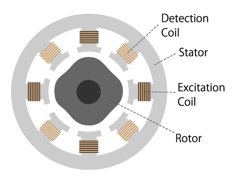 Figure 5. Electromagnetic induction encoder diagram
2-3. What types of rotation and angle information are available?
What is the state of rotation?
Considering an example of a motor, it is stopped, turning clockwise, turning counterclockwise, turning at a constant speed, accelerating, decelerating, and so on.
There are four types of information required to accurately grasp these conditions and to rotate the motor with accuracy.
Rotation amount
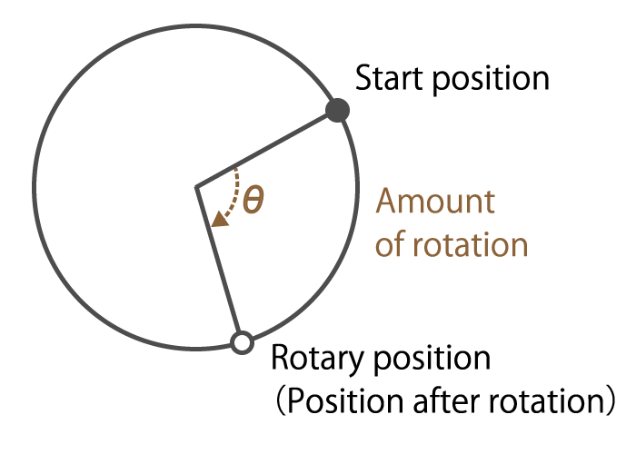 Figure 6. Rotation amount explanation
This is information on how many times the motor shaft angle has moved.
For example, in a brushless DC motor, it is possible to know the amount of rotor rotation by detecting changes in the magnetic poles of the rotor, and to rotate the motor efficiently.
Rotational speed
This is information on how fast the motor shaft has rotated.
As I mentioned in the first episode, the servo motor detects the rotational speed of a brushless DC motor or AC motor, and performs feedback control so that the motor shaft rotates at the speed set by the servo amplifier.
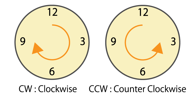
Rotational direction
This is information on which direction (clockwise or counterclockwise) the motor shaft has rotated.
In the system that detects the rotation amount of the motor shaft by the number of pulses output from the encoder, if the rotational direction cannot be recognized, the rotation amount is counted incorrectly.
 Figure 7. Clockwise and counterclockwise
Rotational position
This is information on how many degrees the motor shaft angle is.
As we mentioned in the first part, servo motors and stepper servo motors use encoders to detect the rotation angle and perform feedback control while judging whether the target rotation angle has been reached. As a result, positioning control is performed with high accuracy.
Summary
- An encoder detects the rotation of objects as a physical change amount by the sensor element, and finally transmits rotation/angle information to the outside as an electrical signal.
- An encoder is classified into four types: mechanical, optical, magnetic, and electromagnetic induction types.
- There are four types of information necessary to rotate the motor with high accuracy: rotation amount, rotational speed, rotational direction, and rotational position.
How was it?
In this part, we introduced that there are four types of encoders with different operating principles depending on the physical quantity to be detected. We also introduced that there are four types of rotation information necessary to rotate the motor with high accuracy. I hope you understand the encoder type and mechanism.
In the next part, we will explain an incremental type and absolute type.
Column 1. Encoder for detecting linear displacement
Machine tools that require positioning accuracy such as milling machines and drilling machines use encoders that detect linear displacement. There are the following two methods for detecting linear displacement.
A method of detecting linear displacement with a straight or translational linear encoder.
A linear encoder, also called a linear scale, consists of a scale that serves as a ruler and a head that detects position information.
As with the rotary encoder, there are two detection methods: an optical method that uses light reflection and a magnetic method that uses magnetism.
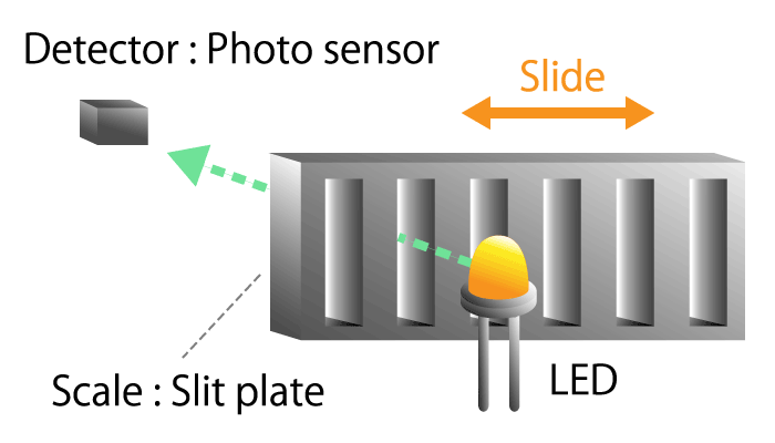 Figure 8a. Optical linear encoder
 Figure 8b. Magnetic linear encoder
A method of converting rotational motion into linear motion, and detecting rotational displacement with a rotary encoder.
The mechanism that converts the rotational movement of the screw into the linear movement of the nut is called the screw feed mechanism. A typical one is a ball screw. When a steel ball is inserted between the screw shaft and the nut and the screw shaft is rotated, the nut moves on a straight line due to the rolling motion of the ball. The linear displacement of the ball screw can be detected using information on the rotational position of the screw shaft and the rotation count.
Ball screws are used in machine tools, measuring instruments, copiers, and printers because they can achieve high positioning accuracy.
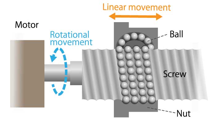 Figure 9. Screw feed mechanism diagram
Basic Knowledge of Encoder