-
제품

-
애플리케이션
-
서포트
-
AKM 소개
#03
Incremental type and absolute type
Basic Knowledge of Encoder
This is the third part of a series that organizes and introduces the knowledge we have acquired so far. In the second part, we introduced the first half of encoder's mechanism. In this part, we will introduce the last half of encoder's mechanism.This is the third part of a series that organizes and introduces the knowledge we have acquired so far.
In the second part, we introduced the first half of encoder's mechanism. In this part, we will introduce the last half of encoder's mechanism.
Contents
Summary
- There are two ways that encoders represent rotation and angle information: a relative angle and an absolute angle.
- The way of representing the relative angle is an incremental method, and the way of representing the absolute angle includes an absolute method and a pseudo-absolute method.
- Both the relative angle and absolute angle have advantages and disadvantages, so it is recommended that you use them properly according to the "purpose of detection".
3-1. What kind of an electrical signal is used to represent rotation and angle information?
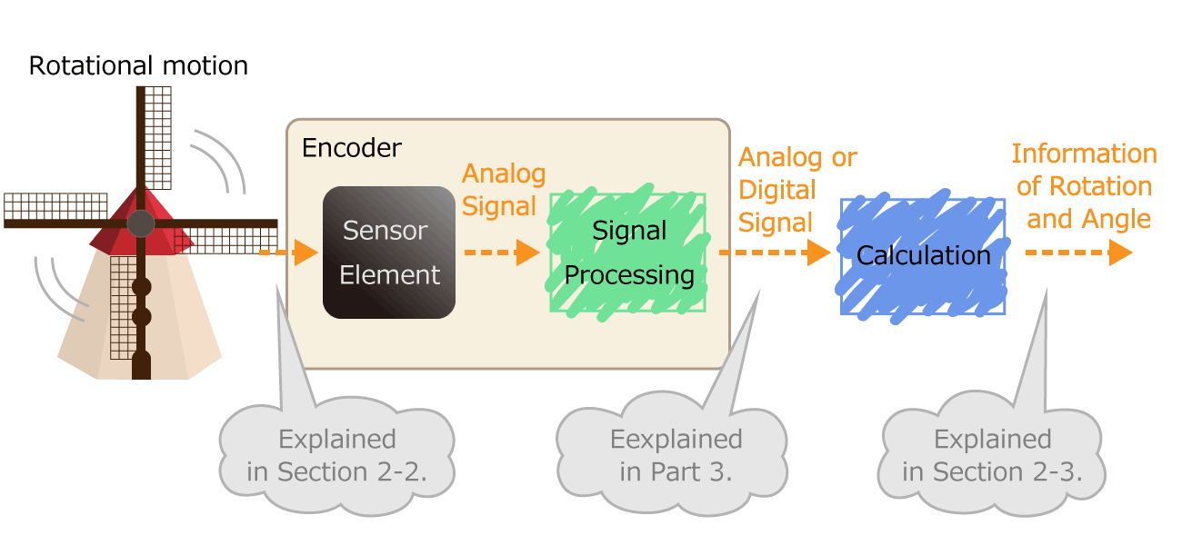 Figure 1. Process of converting rotational motion into rotational information
In the second part, we explained that rotation and angle information is roughly divided into four types. There are two ways that encoders represent rotation and angle information: a relative angle and an absolute angle, and the format of an electrical signal output from encoders differ depending on each expression way.
- Relative angle: How many angles have you moved before and after moving?
- Absolute angle: How many degrees are you in now from the home position?
Incremental method representing a relative angle
An encoder that detects the amount of movement from one position to the next is called a relative angle detection type. If you compare it to a map, it is a relative angle detection type that explains "If you go 100m on this road and go 30m to the right, and then find a convenience store". The relative angle detection type encoder outputs a digital pulse signal according to the rotational operation. Such an output way is called an incremental method.
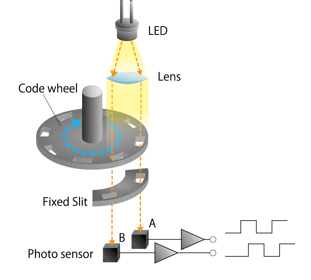
Let's take an optical encoder discussed in the second part as an example. An optical encoder generates pulses when a disk with a slit (hole) in the radial direction rotates.
Counting the number of pulses shows the angular change (movement) of the disk.When four slits are arranged in a row, the number of pulses per rotation is four, so it can be seen that one pulse has rotated 360 ° / 4 = 90 °. If the number of slits is doubled to eight, one pulse rotates 360 ° / 8 = 45 °. If the number of slits, that is, the number of pulses per rotation, is larger, the resolution of the angle change will be higher, and the movement amount can be represented finer.
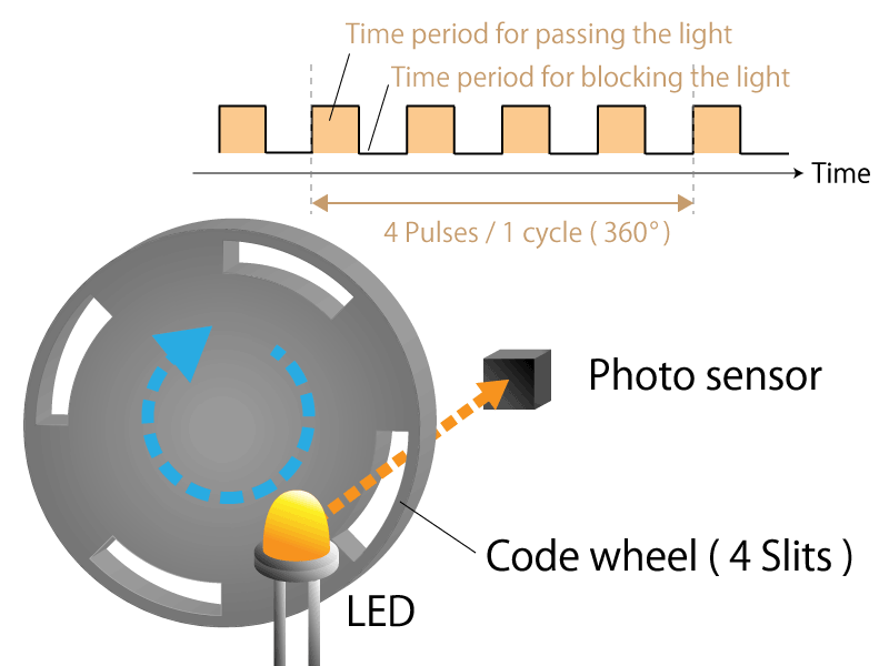 Figure 2a. 4-slit incremental type rotary encoder
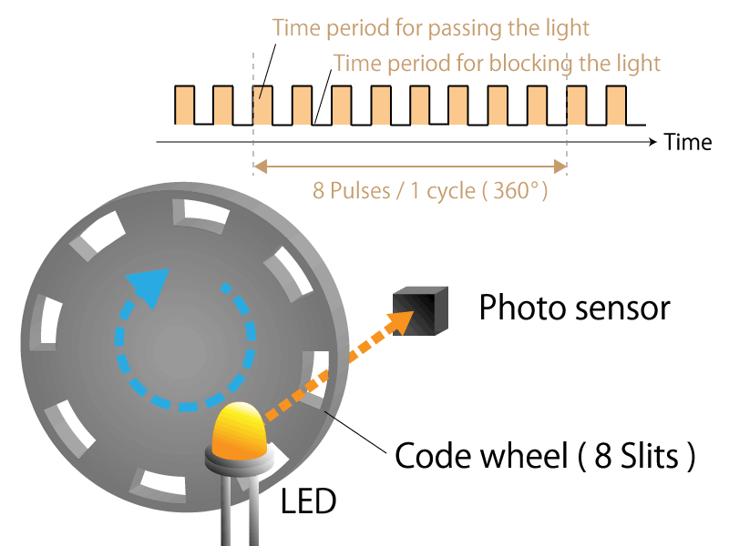 Figure 2b. 8-slit incremental type rotary encoder
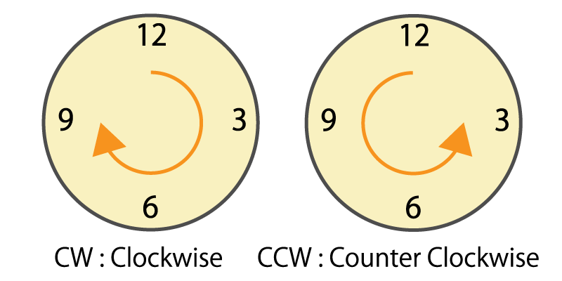
However, this method cannot recognize that the rotational direction has changed.Therefore, two pulses whose phases are shifted by a quarter cycle are generated. These two pulses are generally called phase A and phase B. The rotational direction can be determined depending on which pulse of the phase A or phase B rises first. By subtracting the number of pulses in reverse rotation, the amount of rotation can be accurately determined even if the rotational direction changes.
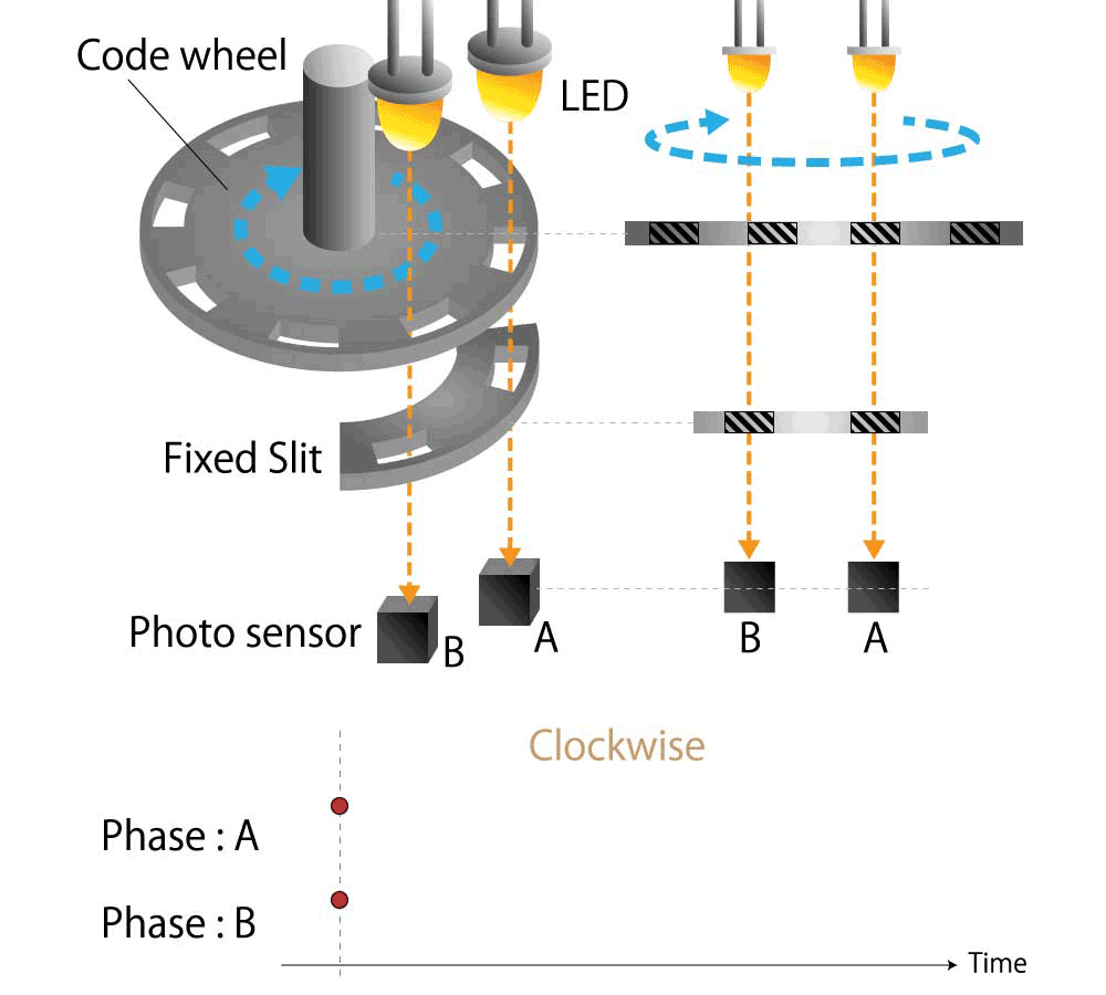 Figure 3a. Waveforms of phase A and B in clockwise
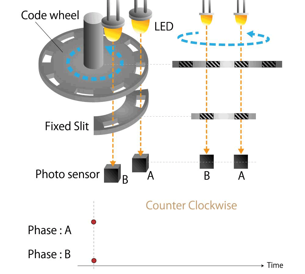 Figure 3b. Waveforms of phase A and B in counterclockwise
Absolute method representing an absolute angle
An encoder that detects how far from the home position is called an absolute angle detection type. When comparing to a map, the absolute angle detection type tells you that there is a convenience store at ABC town, Chiyoda-ku, Tokyo. The absolute angle detection type encoder outputs the current absolute angle in a digital serial code or an analog voltage in response to instructions from the microcomputer. Such an output way is called an absolute method.
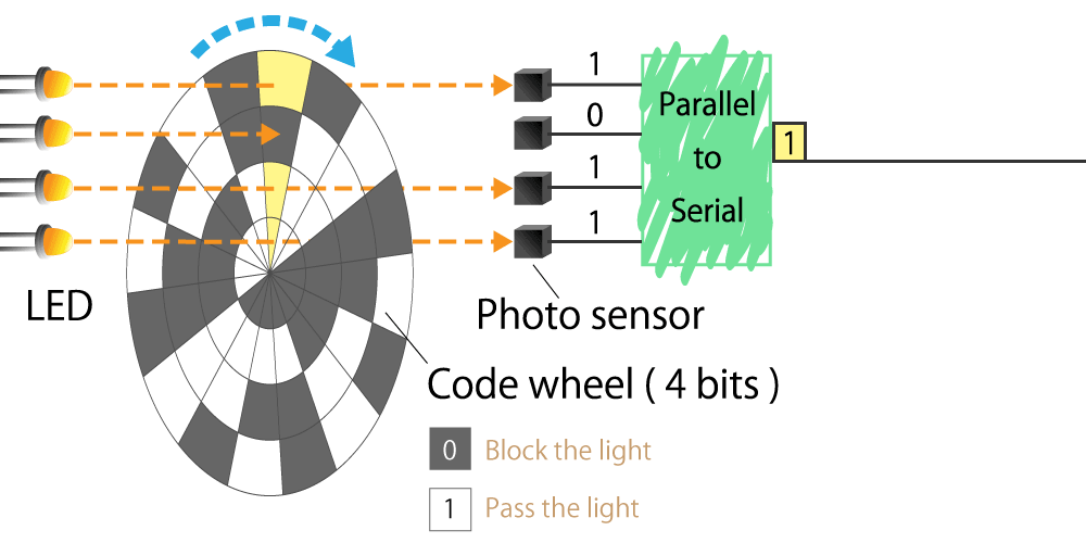
Here again, we will explain its operation with the optical encoder as an example. The incremental method has only one row of slits, while the absolute method has multiple rows. For example, if there are four rows of slits, you can find the absolute position of 16 angles from 0000 to 1111 in binary code (binary number). If there are 5 rows of slits, there are 32 patterns from 00000 to 11111. By doubling the row of slits to eight, you can see the absolute positions of 256 different angles from 00000000 to 11111111. As the number of rows of slits increases, the resolution of the angle change increases, allowing for a finer representation of the amount of movement.
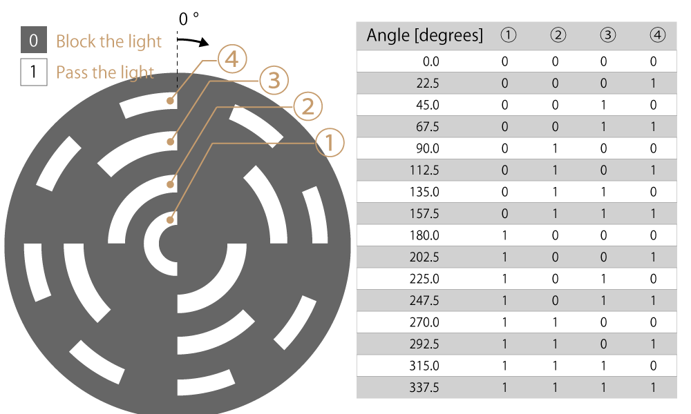 Figure 4a. Absolute rotary encoder with 4 rows of slits
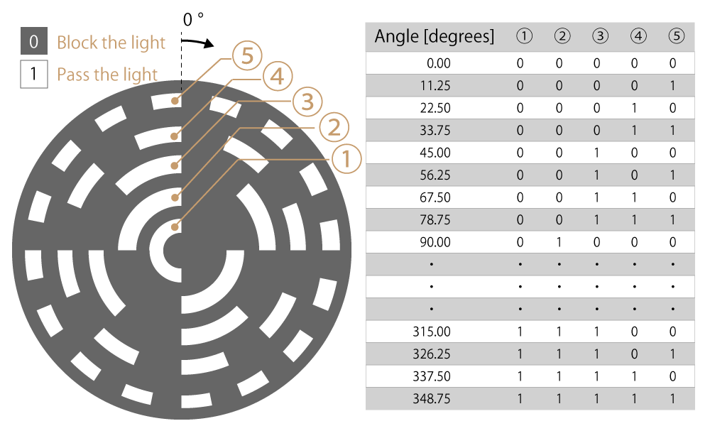 Figure 4b. Absolute rotary encoder with 5 rows of slits
Pseudo-absolute method representing an absolute angle with pulse signal
An absolute angle can also be represented using the incremental method. In addition to the slit row for extracting phase A and B pulses of this method, only one slit is added, and single pulse is generated only once per rotation. This pulse is called a phase Z (meaning Zero). A pseudo-absolute way is a method of representing the absolute angle by detecting the amount of rotation from phase Z pulse, which is the home position of phase A and B pulses.
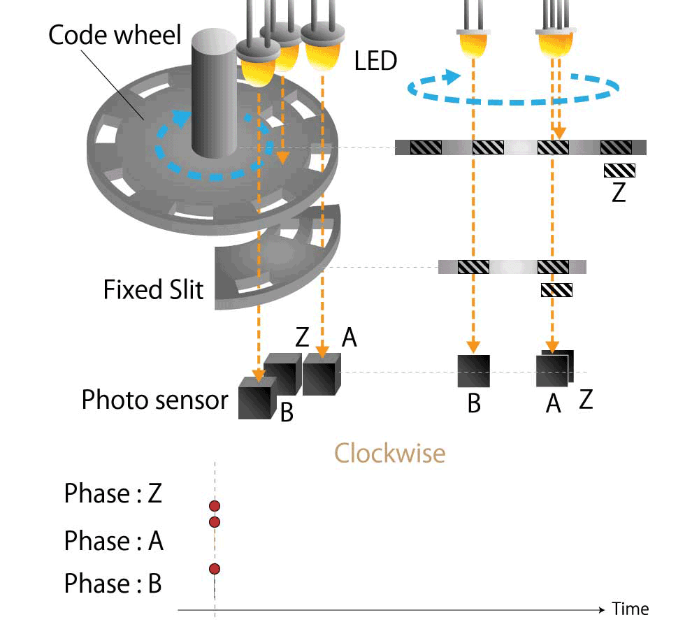 Figure 5a. Waveforms of phase A, B, and Z in clockwise
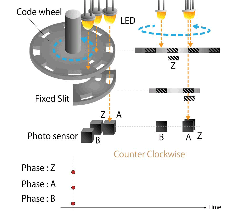 Figure 5b. Waveforms of phase A, B, and Z in counterclockwise
3-2. Advantages and disadvantages of the relative angle and absolute angle
Both relative and absolute angles have advantages and disadvantages.
The incremental method that represents the relative angle has only one row of slits (two rows in the case of pseudo-absolute), so the code wheel can be manufactured at low cost. However, in the case of the absolute method that represents the absolute angle, the slits are arranged in multiple rows, so if the resolution of the angle change is to be increased, the code wheel manufacturing cost will be expensive.
Additionally, If the motor is stopped and restarted after the power is turned off, the absolute method can detect the position at the time of restart. However, in the case of the incremental method and the pseudo-absolute method, the position at the time of restart cannot be detected because the accumulated angle has been deleted.
Furthermore, the absolute method has advantages and disadvantages due to the signal transmission system.
In the absolute method, there are a method of outputting a binary code as a digital signal and a method of converting a binary code to an analog voltage and outputting it. In addition, for digital signals, there is a parallel output that outputs a binary code obtained from multiple slits through multiple signal lines as it is, and there is a serial output that outputs with one signal line while switching multiple signal lines of parallel output one by one sequentially with time.
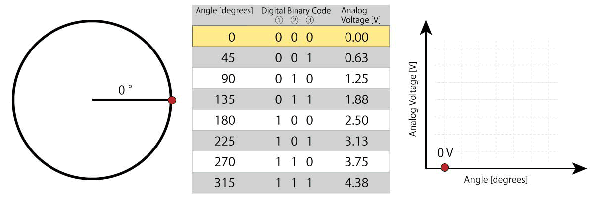 Figure 6. Relationship between angle information, binary code of digital output signal, and analog output voltage
 Figure 7. Parallel output signal and serial converted output signal
Digital signals have the advantage of being resistant to noise during transmission. However, parallel outputs have the disadvantage of increasing the number of signal lines. Since serial output takes time to communicate, if a motor is rotating, the output code may deviate from the current position. Analog signals have the advantage of requiring only one signal line without time delay, but they have the disadvantage of becoming susceptible to noise during transmission.
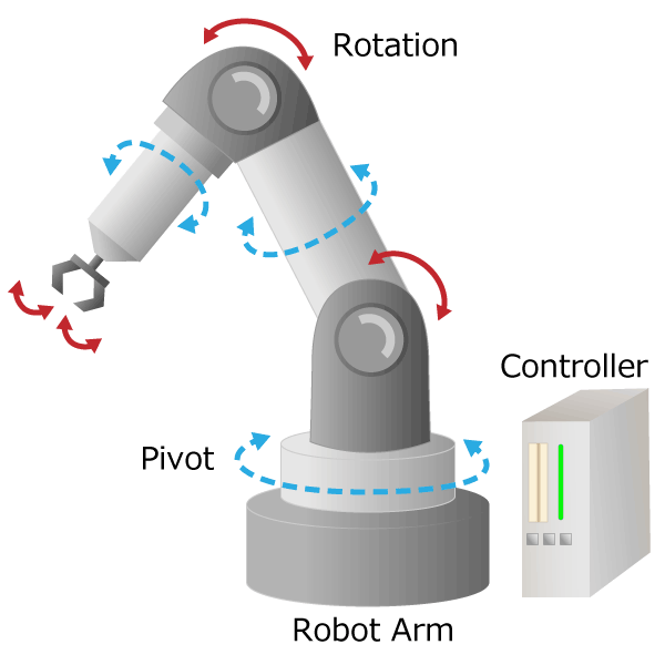
As described above, the relative angle and absolute angle have advantages and disadvantages, you are sure to select the detection type according to the application. For example, rotary angle detection of a motor shaft or a robot arm will require the absolute angle, and rotor magnetic pole detection of a motor will require the relative angle. What position do you want to know and what angle is important? We recommend that you use the relative angle or absolute angle properly according to the "purpose of detection".
Summary
- There are two ways that encoders represent rotation and angle information: a relative angle and an absolute angle.
- The way of representing the relative angle is an incremental method, and the way of representing the absolute angle includes an absolute method and a pseudo-absolute method.
- Both the relative angle and absolute angle have advantages and disadvantages, so it is recommended that you use them properly according to the "purpose of detection".
How was it?
In this part, we introduced the last half of encoder mechanism. I hope you understand that the rotation and angle information is represented by relative angles and absolute angles.
In the next part, we will explain the mechanism and features of the optical encoder.
Basic Knowledge of Encoder