-
Products

-
Applications
-
Support
-
About AKM
Latch type Hall IC
#09 Basic Knowledge of Magnetic Sensor
A Hall IC outputs high/low digital output, and a Hall IC that alternately detects both S pole and N pole magnetic fields is called a latch type Hall IC. This page describes application examples of latch type Hall ICs.
What is a latch type Hall IC?
Features
Latch-type Hall ICs are a sensor that operates by switching between the S and N magnetic poles of a magnet (see "Principles and Types of Hall ICs"). It has long been widely used to detect the magnetic poles of the rotor magnet of DC brushless motors. In recent years, it has also been used for applications such as simple rotary encoders (AKM's EW Hall IC is highly sensitive and operates at high speed, and is widely used in DC brushless motors).
Typical application examples
(1) DC brushless motor
A DC brushless motor is a highly efficient and maintenance-free motor that rotates with direct current. The motors are used as fan motors for air conditioners and main motors for white goods. For details on the principle, please check "Ultra-high sensitivity Hall element".
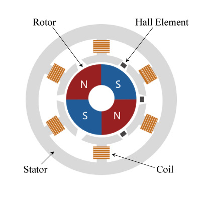
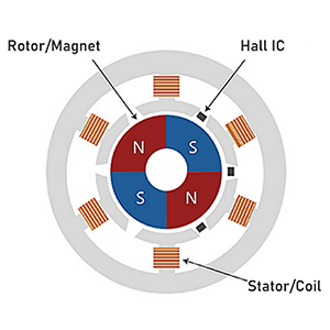
The main components of a DC brushless motor are magnets, Hall ICs, and coils.
The rotor is a magnet and is placed in the center as shown in Figure 1. The stator is a coil and current is turned on and off according to the output signal of each Hall IC. The Hall IC is installed in a position where the maximum magnetic field from the rotor magnet can be obtained and detects the magnetic field of the rotor magnet. The Hall IC controls the energized coil in a timely manner, that is, switches the location and direction of the magnetic field generated by the coil, and repeats the attraction and repulsion with the rotor magnet, so that the rotor magnet continues to rotate in one direction.
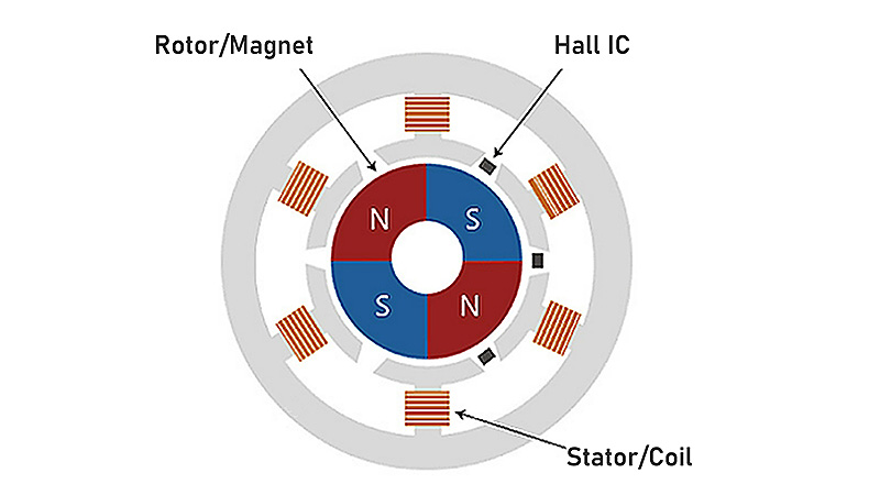 Figure 1. Principle diagram of DC brushless motor
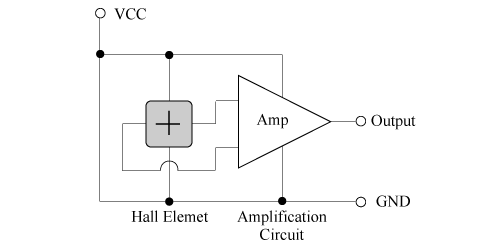
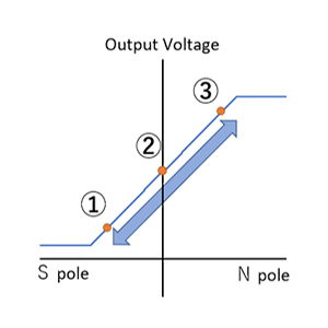
This is basically a configuration in which a Hall element of the ultra-high sensitivity Hall element (1) DC brushless motor is replaced with a Hall IC. By using the Hall IC, an amplifier circuit, which is the step following the Hall element, becomes unnecessary. Since the output voltage is a digital output of high and low, it has the advantage of excellent noise resistance, especially when the wiring from the motor to the microcontroller is long. The output signal can be input directly to the microcontroller, making it easier to use.
(2) Rotary encoder (incremental type)
A rotary encoder is a sensor mechanism that measures rotational position, rotation angle, and rotation speed. It is used to control the rotation of motors and detect the angular position of rotating objects.
The main components of a rotary encoder are a multipolar magnet, two Hall ICs, and a rotating shaft.
Attach a cylindrical or donut-shaped multipolar magnet to the rotating shaft so that it is parallel to the direction of rotation.
Regarding the positional relationship between the two Hall ICs, if one pole pair of the S and N poles of the magnet is considered to be one cycle, the Hall ICs are placed at positions shifted by 1/4 cycle from each other.
*Even a single Hall IC can detect the switching of the magnet's poles, so it is possible to detect the rotational position and rotation angle. However, by carefully arranging the two Hall ICs, it is possible to improve the rotation angle detection resolution and detect the rotation direction.
In the example in Figure 2a, the rotating object is rotating clockwise. When the magnet rotates, the output of these two Hall ICs changes every 1/4 cycle, and using this change in output, it is possible to detect how much the rotating object has moved. When the magnet rotates further, the Hall IC outputs a pulse train, and by counting the number of pulses, the rotation speed can be detected.
In addition, by performing logical operations on the outputs of two Hall ICs, it is also possible to output the rotation direction of the magnet in binary form.
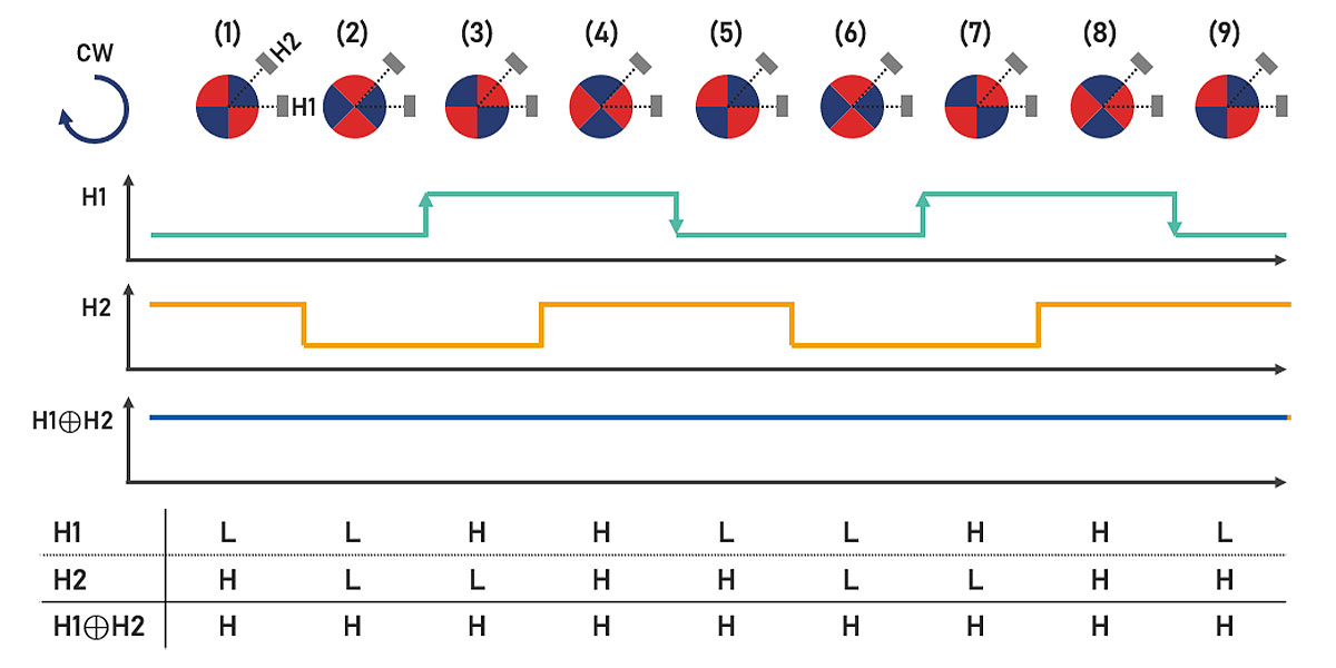 Figure 2a. Incremental rotary encoder rotation and output waveform during CW
In the example in Figure 2b, the rotating object is rotating anticlockwise. As in Figure 2a, the output changes in 1/4 cycles, but the major difference from the clockwise rotation is that the order of output switching is reversed.
For example, when rotating clockwise in Figure 2a, both Hall ICs have a high output at positions (4) and (8), but when rotated a quarter of a turn at positions (5) and (9), both Hall ICs have a high output. H1: L, H2: H.
On the other hand, when turning anticlockwise, both Hall ICs have high output at positions (7) and (3), but when rotated 1/4, positions (6) and (2) are both H1: H, H2: L, that is, the output of H2 is switched first, and the order of output switching is reversed.
In this way, by knowing the order in which the Hall IC's output switches, it is possible to detect which direction it is rotating. For example, by using the rise and fall of H1 as a trigger to calculate the XOR of the two outputs, it is possible to obtain an H or L result, thereby being able to determine the direction of rotation.
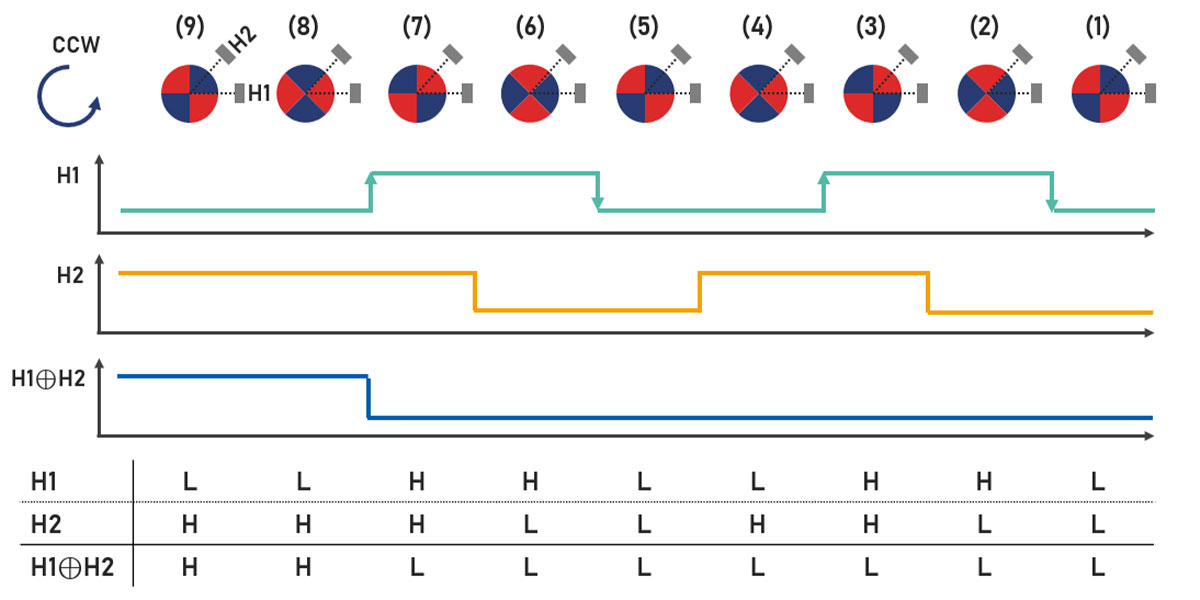 Figure 2b. Incremental rotary encoder rotation and output waveform during CCW
Why latch type Hall ICs are suitable for rotation detection
When a switch type Hall IC is used instead of a latch type Hall IC as a rotating body detection sensor, the same number of pulses as the latch type are output according to the number of magnet poles, but the duty ratio deteriorates from that of the latch type. (Figure 3).
This is because the latch type has Bop/Brp set symmetrically across the 0 magnetic field, resulting in a duty ratio of 50%, whereas the switch type has Bop/Brp set to the same pole. In the case of unipolar detection, the N pole region has a high output, so the low time is shortened.
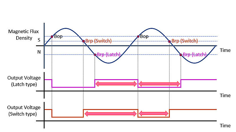 Figure 3. Difference in output voltage when detecting the magnetic field of a rotating magnet between a latch type Hall IC and a switch type Hall IC
What makes AKM different ?
You may be surprised to find AKM's Hall sensors in such products as these! Hall sensors are used in familiar products such as air conditioners, washing machines, and smartphones. Here we will explain why AKM's Hall sensors are widely chosen by many people.
 Hall Sensors