-
Products

-
Applications
-
Support
-
About AKM
Principles and types of Hall ICs
#07 Basic Knowledge of Magnetic Sensor
Hall ICs provide high/low digital output and are widely used in a variety of white goods and industrial equipment because the output can be easily processed by the subsequent drivers and microcontrollers. This page explains the principles and types of Hall ICs.
Principle of Hall IC
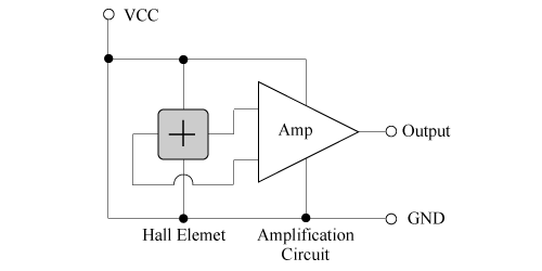
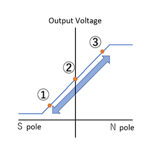
A Hall IC consists of a Hall element and a signal processing IC. This sensor compares the output voltage of the Hall element using a signal processing IC, converts it into a High/Low signal, and outputs it (Figure 1). For this reason, unlike Hall elements, it is not possible to obtain detailed information such as "how strong a magnetic field was applied.'' However, you can easily get digital outputs such as "Magnet present/absent".
Additionally, since the output voltage range of a Hall IC is determined by the output pull-up voltage, when the voltage is pulled up to the power supply voltage, it can be more easily received by the microcontroller by matching the Hall IC power supply voltage to the input voltage range of the subsequent microcontroller.
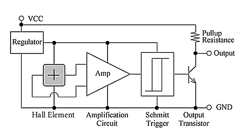 Figure 1. Operating circuit (reference diagram)
Hall IC types
Hall ICs are divided into switch type Hall ICs (unipolar detection/bipolar detection) and latch type Hall ICs, depending on the difference in the magnetic poles they detect. Depending on the drive method of the internal IC, they can be divided into a continuous drive type and an intermittent drive type.
Classification based on the difference in magnetic pole detected
Switch type Hall IC
(1) Unipolar detection
This Hall IC operates with only the S pole (or only the N pole). In S pole operation, the output is high when a N pole magnetic field is applied or when the S pole is far enough away that there is no magnetic field.
As shown in Figure 2a, the S pole of the magnet is brought closer to the Hall IC, and when the magnetic field applied to the Hall IC exceeds Bop in Figure 2b, the output becomes Low.
Then, with the output low, move the magnet away from the Hall IC, and when the applied magnetic field at the S pole is less than Brp, the output will become high.
* Asahi Kasei Microdevices Corporation (AKM)'s switch type Hall IC is available only for S pole detection.
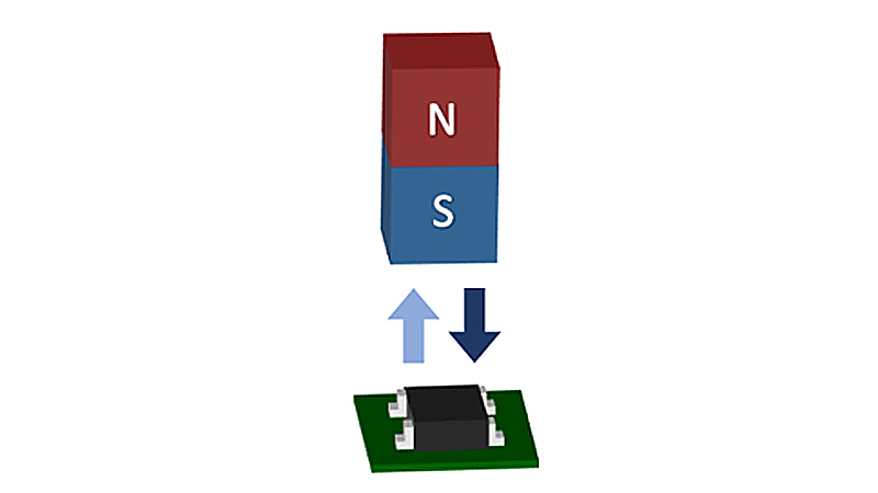 Figure 2a. Example of arrangement of S pole sensing Hall IC and magnet
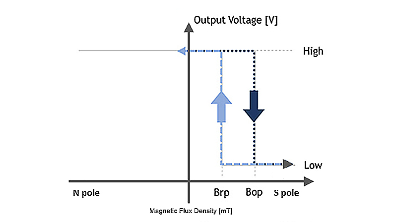 Figure 2b. Operation of the S pole sensing Hall IC
(2) Bipolar detection
This Hall IC operates with both S and N poles. When the magnets are far enough apart and there is no magnetic field, the output will be High.
If the magnetic field applied to the Hall IC exceeds Bop in Figure 3b when the magnet is brought close to it, regardless of the S or N pole, as shown in Figure 3a, the output will become Low.
When the magnet is moved away until the applied magnetic field falls below Brp while the output is low, the output will become high.
Hall ICs with bipolar detection are useful when the magnet can be installed in any direction.
* There is no lineup for AKM products.
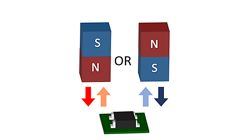 Figure 3a. Example of arrangement of bipolar detection Hall IC and magnet
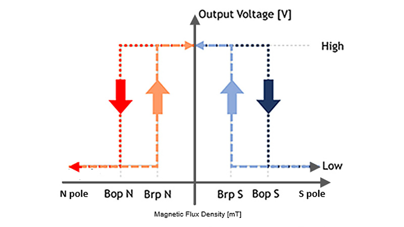 Figure 3b. Operation of bipolar detection Hall IC
Among bipolar detection Hall ICs, there is also a two-output type Hall IC with separate S and N pole output terminals, as shown in Figure 3c. In this Hall IC, when the magnet is far away and there is no magnetic field, both the S pole output and the N pole output are High.
When magnets are brought close to each other and the output of the pole that is brought close exceeds Bop, it will switch to Low (*1).
A 2-output type Hall IC has two output terminals, S pole and N pole, so it is useful for detecting the polarity of the magnet.
* There is no lineup for AKM products.
*1 Even if two magnets, S and N poles are brought close together and the magnetic field is applied, both output terminals will not become High at the same time because the magnets cancel each other's magnetic fields.
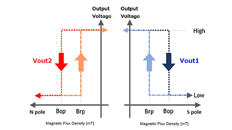 Figure 3c. Operation of bipolar (2 output) detection Hall IC
Latch type Hall IC
This Hall IC operates by alternately detecting magnetic fields from both the S and N poles. Generally, the S pole side is Bop and the N pole side is Brp.
When a S pole magnetic field is applied to the Hall IC exceeding Bop, the output becomes Low. After that, as shown in Figure 4a, the output remains Low even if the magnet rotates and the magnetic field that is applied to the Hall IC decreases to the state of no magnetic field (Figure 4b).
When the magnet rotates further and an N pole magnetic field is applied to the Hall IC exceeding Brp, the output switches to High. After that, even if the magnet rotates and the magnetic field changes, the output of the Hall IC will remain until a S pole magnetic field that is applied reaches the level greater than Bop.
This Hall IC is called a latch type because its output is held (latched) until the polarity of the applied magnetic field changes.
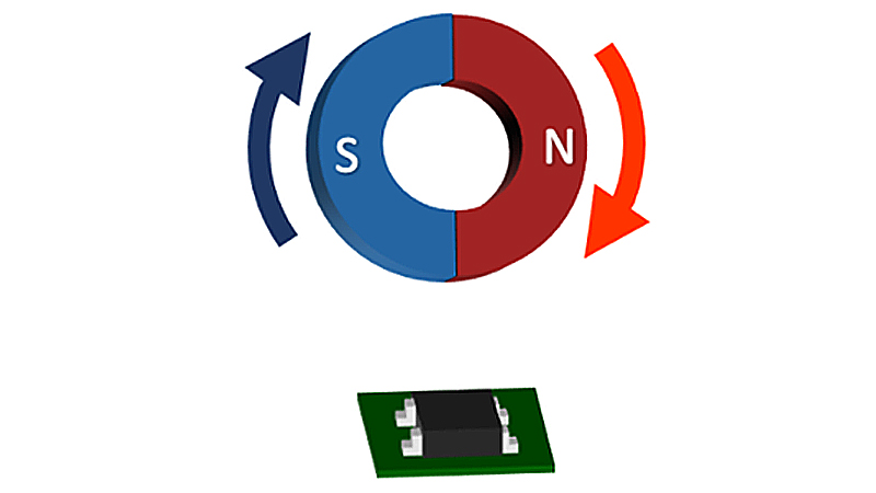 Figure 4a. Example of arrangement of latch type Hall IC and magnet
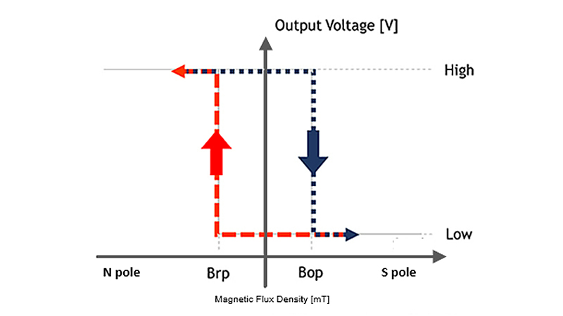 Figure 4b. Operation of latch type Hall IC
Classification by Hall IC drive method
Continuous drive Hall IC
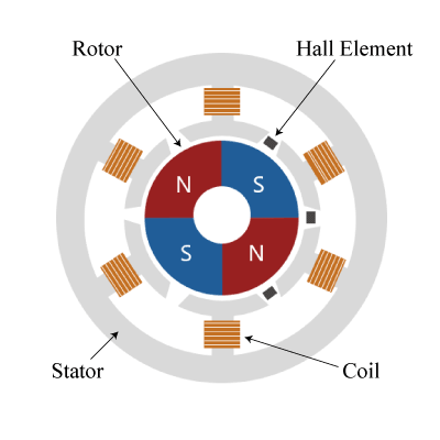
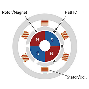
Common Hall ICs are of this type. The are used in applications where the magnetic field changes quickly, such as magnetic field detection in motors.
Intermittent drive Hall IC (low power consumption Hall IC)
It is used in battery-powered applications such as mobile devices that are designed to require low power consumption. As shown in Figure 5, the Hall IC periodically repeats SLEEP and AWAKE, detects the magnetic field during AWAKE, determining the output, and maintains the output during SLEEP. The longer the SLEEP time, the lower the power consumption, but it is not suitable for applications where the magnetic field changes rapidly. A typical application is detection of opening/closing of mobile computers.
* There is no lineup for AKM products.
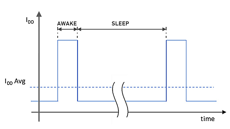 Figure 5. Example of intermittent drive operation
◆Tips
Why does hysteresis exist in Hall ICs?
For Hall ICs, the value of the magnetic field at which the output changes from High to Low (Bop) and the value of the magnetic field at which the output changes from Low to High (Brp) are different. This difference in magnetic fields is defined as hysteresis (Bh) (Bh = Bop-Brp). Hysteresis is intentionally set to prevent Hall IC malfunction.
If hysteresis is not set, Bop=Brp is established. When just this magnetic field is applied, minute changes in the magnetic field (magnetic field noise) can cause the Hall IC output to repeat high and low. This phenomenon is called chattering (Figure 6a). Therefore, hysteresis is provided between Bop and Brp to prevent chattering, thereby preventing malfunctions (Figure 6b).
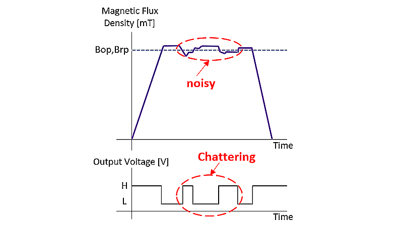 Figure 6a. Noise impact without Hall IC hysteresis.
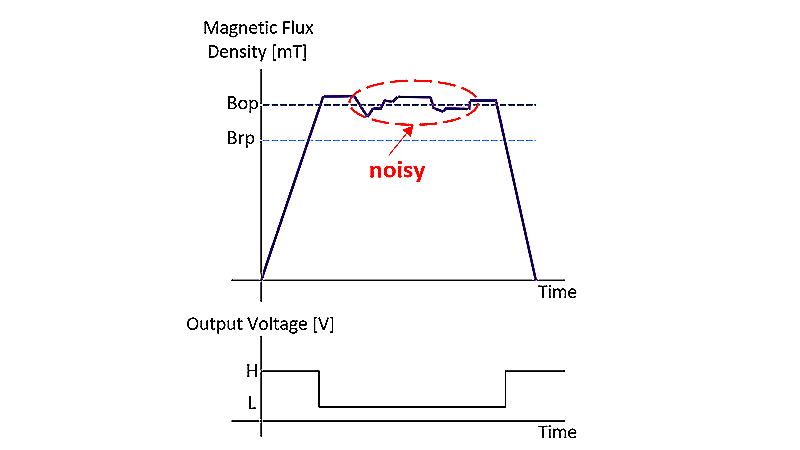 Figure 6b. Effect of setting hysteresis in Hall IC
What makes AKM different ?
You may be surprised to find AKM's Hall sensors in such products as these! Hall sensors are used in familiar products such as air conditioners, washing machines, and smartphones. Here we will explain why AKM's Hall sensors are widely chosen by many people.
 Hall Sensors