-
Products

-
Applications
-
Support
-
About AKM
Low Drift Hall Element
#05 Basic Knowledge of Magnetic Sensor
Low Drift Hall Element Gallium Arsenide (GaAs)
Three types of Hall elements (ultra high-sensitivity, high-sensitivity, and low drift) were introduced in the section Types and Principles of Hall Elements.
This page explains some example applications of the low drift Hall Element specifically.
Semiconductor Materials
(AKM's product name)
Gallium Arsenide: GaAs
(HG series)
Features
GaAs has the most stable temperature characteristic among the three Hall element types. It shows the temperature characteristics more stable by using constant current drive rather than constant voltage drive.
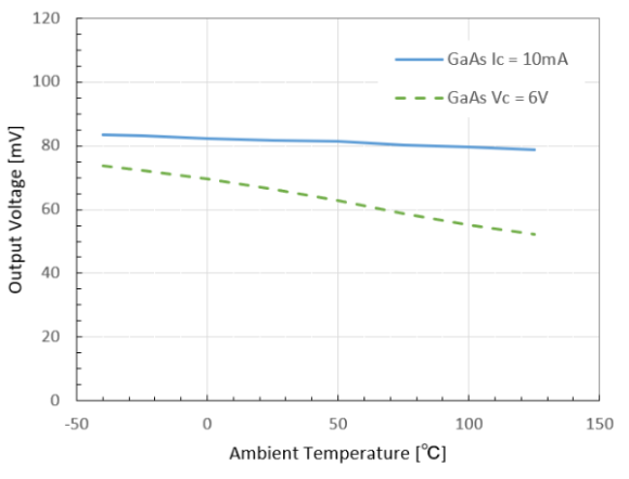 Figure 1. Output Voltage of GaAs Hall Element (B=50mT)
Typical Applications
(1) Image Stabilization of Smartphone Camera
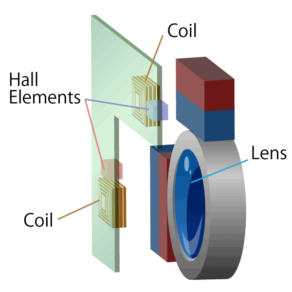
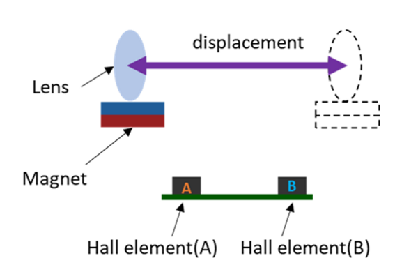
Image stabilization is a mechanism to suppress subject shake by moving the lens in a direction to adjust camera shake movement. It is used in digital still cameras, single-lens reflex cameras, and smartphones. The movement of camera shake is detected by a gyro sensor, and the amount of lens movement (lens position) is determined according to the amount of camera shake. The Hall element detects a position of the lens in an image stabilizer.
 Figure 2. Structure of Image Stabilizer
The principle of the image stabilizer using the Hall element is described below.
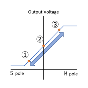
The magnet movement direction is aligned with the magnet magnetization direction, and the Hall element is placed just at the boundary of magnetic poles. With this arrangement, there is a region where the magnetic field applied to the Hall element varies proportionally to the movement of magnets around the boundary between the S and N poles of magnets. The position of magnets can be precisely detected within this range.
(Magnet movement ∝ Magnetic field change ∝ Hall output voltage)
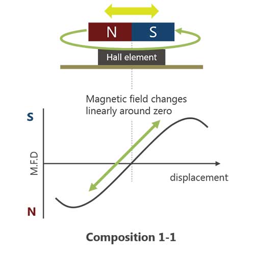 Figure 3. Principle of Movement Detection
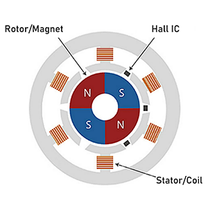
The main components of an image stabilizer are a magnet, a Hall element for detecting the position of lens, and a coil for driving lens. In order to suppress subject shake due to camera shake, current is applied to the coil and lens is moved by the repulsion and attraction force of the coil and magnet. When the Hall element detects the position of magnet attached to the lens, it can detect the position of the lens and move the lens to a correct position.
 Figure 4-1. Detection of lateral movement
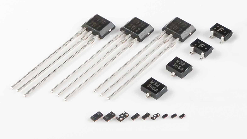
By using a GaAs Hall element with stable temperature characteristics, stable position detection can be performed regardless of the ambient temperature. In addition, the Hall element is available in very small sizes, so it can be applied to smartphones and other products that require high-density mounting.
 Figure 4-2. Detection of vertical movement
(2) Open-Loop Current Sensor
A magnetic current sensor detects the amount of current by measuring the magnetic field (i.e. magnetic flux density) generated around the current being measured. Open-loop current sensors have many uses, such as in inverter controllers of air conditioners and DC detectors of photovoltaic power conditioners. The magnetic flux density generated from the current is expressed by the following equation according to Biot-Savart's law.
 Figure 5. The Biot-Savart’s Law
B=μ0×(1/(2×π×r))×I
B: Magnetic Flux Density
μ0: Vacuum Permeability
r: Distance from Current Line
I: Current
As can be seen from the equation, the magnetic flux density is proportional to the current. The amount of current flowing through the conductor can be determined accurately by using the Hall element to measure the magnetic field generated by the conductor. This method is different from the conventional method of measuring the voltage by inserting a shunt resistor (a small resistor for current-voltage conversion) directly into the current path being measured. It has the advantage that it can be measured without loss, since the current to be measured and the sensor signal are isolated from each other.
 Figure 6. Open-Loop Current Sensor
As can be seen from the equation, the magnetic flux density is proportional to the current. The amount of current flowing through the conductor can be determined accurately by using the Hall element to measure the magnetic field generated by the conductor. This method is different from the conventional method of measuring the voltage by inserting a shunt resistor (a small resistor for current-voltage conversion) directly into the current path being measured. It has the advantage that it can be measured without loss, since the current to be measured and the sensor signal are isolated from each other.
What makes AKM different ?
You may be surprised to find AKM's Hall sensors in such products as these! Hall sensors are used in familiar products such as air conditioners, washing machines, and smartphones. Here we will explain why AKM's Hall sensors are widely chosen by many people.
 Hall Sensors