-
Products

-
Applications
-
Support
-
About AKM
What's a Magnetic Sensor?
#01 Basic Knowledge of Magnetic Sensor
A magnetic sensor is a sensor that detects the magnitude of magnetism and geomagnetism generated by a magnet or current. There are many different types of magnetic sensors.
This section explains the typical sensor types and their features.
Coiled
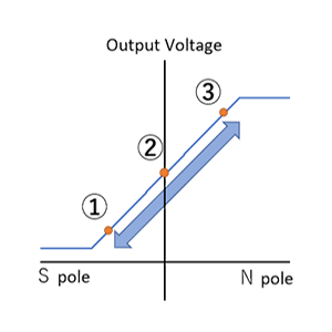
Coils are the simple magnetic sensors that can detect changes of the magnetic flux density. As shown in Figure 1, when a magnet is brought close to the coil, the magnetic flux density in the coil increases by ΔB. Then, an induced electromotive force/induced current that generates a magnetic flux in a direction that hinders an increase in magnetic flux density is generated in the coil. Conversely, moving the magnet away from the coil reduces the magnetic flux density in the coil, so induced electromotive force and induced current will be generated in the coil to increase the magnetic flux density.
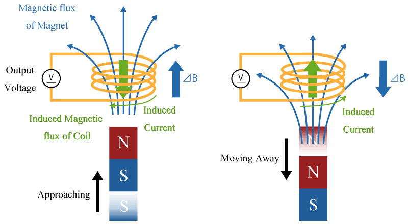 Figure 1. Principle Diagram of Coil
Also, since there is no change in the magnetic flux density when the magnet is not moved, no induced electromotive force or induced current will be generated. By measuring the direction and magnitude of this induced electromotive force, it is possible to detect the change in magnetic flux density.
Because of its simple structure, a coil is not easily damaged. However, the output voltage depends on the rate of change of the magnetic flux. It may not be possible to use a coil to detect a fixed magnet or magnetic flux that changes very slowly.
Reed Switch
A reed switch is a sensor in which metal pieces (reed) extending from both the left and right sides are enclosed in a glass tube with a gap at the overlapping position of the reeds. When a magnetic field is applied externally, these reeds are magnetized. When the reeds are magnetized, the overlapping parts attract each other and come into contact, then the switch turns on.
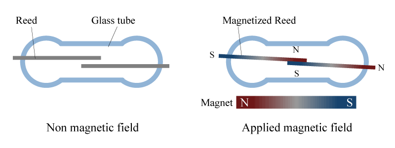 Figure 2. Principle Diagram of Reed Switch
Hall Elements
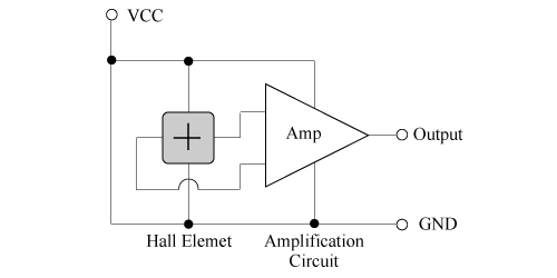
A Hall element is a device that uses the Hall effect. “Hall” came from Dr. Hall's name for discovering Hall effect. It is based on the phenomenon that the electromotive force appears in the direction orthogonal to both the current and the magnetic field when applying a magnetic field perpendicular to the current to the object through which current is flowing.
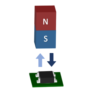
When a current is applied to a thin film semiconductor, a voltage corresponding to the magnetic flux density and its direction is output by the Hall effect. The Hall effect is used to detect a magnetic field, (shown in Figure 3).
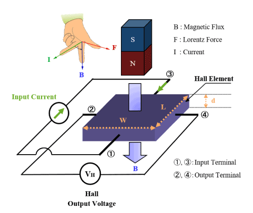 Figure 3. Principle Diagram of Hall Element
Hall elements can detect a magnetic field even in the case of a static magnetic field with no change in magnetic flux density. Therefore, Hall elements are used in various applications, such as non-contact switches used in combination with magnets, angle sensors, and current sensors. Geomagnetic sensors using Hall elements are widely used in smartphones and other applications.
Magnetoresistive Element
An element that detects a magnetic field using a material, that resistance changes when magnetic force is applied, is called a magnetoresistive, (MR), element.
Other than semiconductor magnetoresistive element, (SMR), there are three kinds of sensors as representative examples of the magnetoresistive element using a ferromagnetic thin film material such as anisotropic magnetoresistive element, (AMR), giant magnetoresistive element, (GMR), and tunnel magnetoresistive element, (TMR).
Semiconductor Magnetoresistive Element (SMR)
Whereas the Hall element is a sensor that measures the Hall voltage generated by the Lorentz force, the magnetoresistive element is a sensor that utilizes the change in the resistance value caused by the Lorentz force. Figure 4 shows how the resistance value of an N-type semiconductor magnetoresistive element (SMR: Semiconductor Magnetoresistive), which AKM also produces, changes. Metal electrodes are placed on a semiconductor thin film in the structure of SMR. When a clockwise current as shown in the figure flows through the semiconductor thin film, electrons which are carriers of N-type semiconductors flow counterclockwise, and the velocity of the vector is assumed as "v". When applying a magnetic field B oriented as shown in the figure, electrons undergo Lorentz force and the path becomes longer as being bent, so that the resistance value increases.
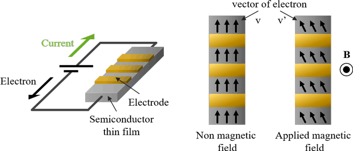 Figure 4. Principle Diagram of Semiconductor Magnetoresistive Element
Sensors using SMR elements are used for detecting rotation of gears.
Anisotropic Magnetoresistive Eelement (AMR)
The scattering degree of electro changes between the case (a) where the magnetization direction of the ferromagnetic film is parallel to the direction of current and the case (b) where the direction of magnetization is vertical to the current direction. Therefore, the resistance value also changes.
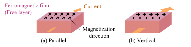 Figure 5. Principle Diagram of AMR
Giant Magnetoresistive Element (GMR)
In the case of a laminated film of ferromagnetic material, (pinned layer), nonmagnetic metal and ferromagnetic material, (free layer), the scattering degree of electron changes depending on if the direction of magnetization of the pinned layer and the free layer are antiparallel (a) or parallel (b). Therefore, the resistance value changes.
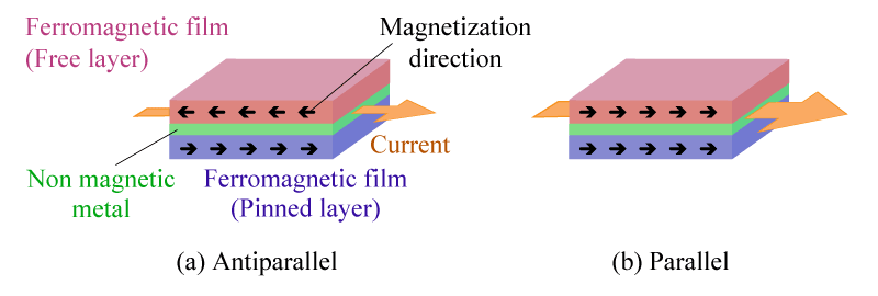 Figure 6. Principle of Diagram of GMR
Tunnel Magnetoresistive Element (TMR)
In the case of a laminated film of ferromagnetic material, (pinned layer), insulator and ferromagnetic material, (free layer), the proportion of electrons passing through the insulator changes due to the tunnel effect and the resistance value changes depending on if the direction of magnetization of the pinned layer and the free layer are antiparallel (a) or parallel (b).
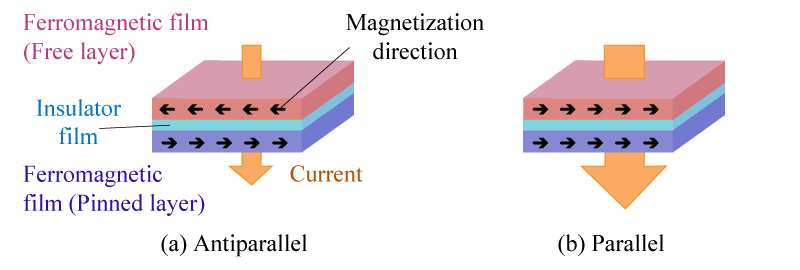 Figure 7. Principle of Diagram of TMR
What makes AKM different ?
You may be surprised to find AKM's Hall sensors in such products as these! Hall sensors are used in familiar products such as air conditioners, washing machines, and smartphones. Here we will explain why AKM's Hall sensors are widely chosen by many people.
 Hall Sensors