-
Products

-
Applications
-
Support
-
About AKM
Switch type Hall IC
#08 Basic Knowledge of Magnetic Sensor
A Hall IC is a sensor providing high/low digital output and detects the strength of a magnetic field is called a switch type Hall IC. This page describes application examples of switch type Hall ICs.
What is a switch type Hall IC?
Features
Switch type Hall ICs are divided into three types depending on the magnetic field they detect: unipolar detection, bipolar detection, and bipolar detection (2 outputs) (see "Principle and Types of Hall ICs"). Basically, they turn ON/OFF according to the strength of the applied magnetic field. Taking advantage of this characteristic, this device is used to detect the presence or absence of magnets and whether magnets are approaching and/or passing through.
Typical application examples
(1) Position detection sensor
Position detection sensors detect the origin and end points of safety covers and actuators for home appliances and industrial equipment.
Similar sensors include contact type mechanical switches and non-contact type optical switches (photo interrupters, etc.), while the following advantages become available by using Hall ICs.
- Longer lifespan than mechanical switches as there are no mechanical contacts, eliminating the wear problem
- Advantageous over optical switches as magnetic fields can be detected even when dust and dirt accumulate
- Since it operates according to the presence or absence of a magnet without any contact, waterproof design is possible, facilitating maintenance work.
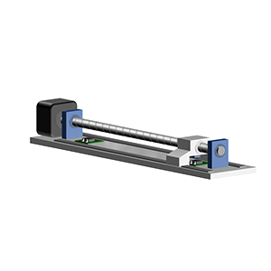
Below is a brief explanation of ball screws (for details, please check the column, "Basic Encoder Knowledge #02 Encoder Types and Mechanisms'').
A ball screw converts rotational motions into linear motions by rotating a screw shaft attached to a motor and moving a nut back and forth. Since the encoder attached to the motor can accurately measure the distance travelled by the nut, it is used in industrial equipment. Additionally, by detecting the origin of the nut, it is possible to prevent deterioration in position accuracy due to failure or aging. The end point detection is also installed to prevent the nut from overrunning and colliding in the event of actual failure or aging.
The main components of a ball screw position sensor are a motor, a screw shaft, a nut, a magnet, and two Hall ICs (and a bearing, a guide rail, and a base).
Figure 1a shows examples of the ball screw origin detection (1) and the end point detection (2).
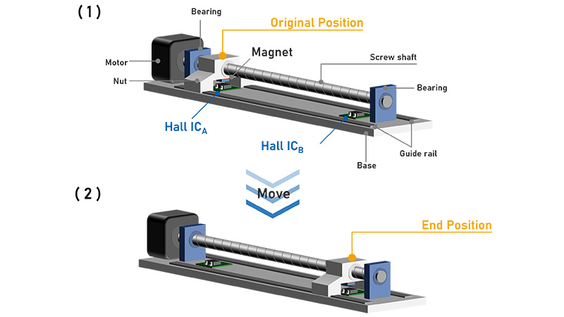 Figure 1a. Ball screw example
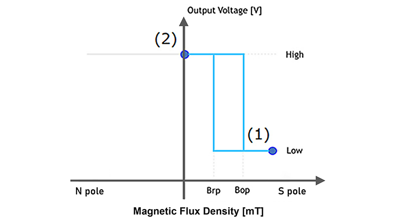 Figure 1b. Operation diagram of Hall IC A
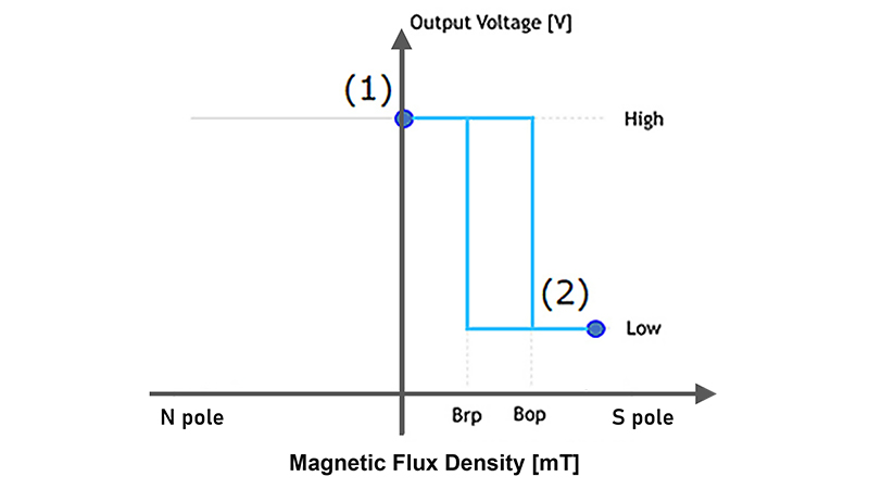 Figure 1c. Operation diagram of Hall IC B
Install a magnet on the nut side and two Hall ICs on the fixed base side at the origin and end positions.
For Hall IC A, when the nut is at the home position ((1)), the magnetic field from the applied magnet exceeds Bop, so the output is Low, enabling it to identify the home position (Figure 1b).
When the nut moves due to the rotation of the screw shaft and reaches the end position (at the time of (2)), Hall IC B exceeds Bop and the output becomes Low (Figure 1c).
For industrial equipment, there are many applications that require high-precision position detection and applications that operate at high speed, so these EW products from AKM, which can respond quickly, are recommended.
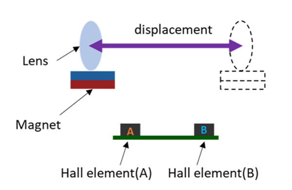
(2) Fuel gauge/fluid level sensor
Fuel gauges and liquid level gauge sensors notify you when the remaining amount of liquid fuel or water tank has reached a predetermined amount. Since there is no mechanical contact and the electrical circuit can be installed outside the tank, it has the advantage of being usable even with flammable liquids. Generally, it is used to detect the upper limit (full) or lower limit (empty) of the liquid level in a tank. As an application example, by arranging Hall ICs in an array, it is possible to create a mechanism that can detect the liquid level in multiple stages.
Below is an example of the detection of the lower limit position of the liquid level. The main components of a liquid level sensor are a magnet, Hall IC, and float.
Attach the magnet to the float with the S pole facing the Hall IC. Then, place the Hall IC at the height of the liquid level you want to detect (see (1) in Figure 2a).
When there is enough liquid in the tank, the magnetic field is small enough because the magnet and Hall IC are far apart, and the Hall IC is in the High state. As the liquid decreases over time, the magnet moves down to the Hall IC position, the magnetic field applied to the Hall IC exceeds Bop, and the output of the Hall IC changes to Low. (Figure 2b)
This change in output can be used to detect the remaining amount of liquid.
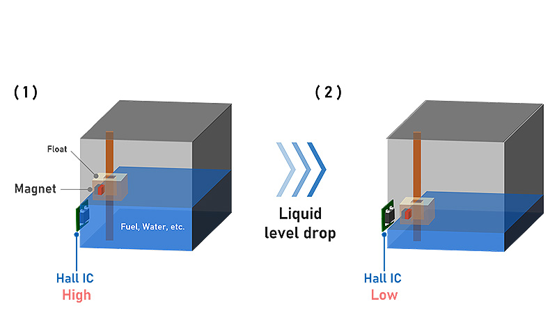 Figure 2a. Example of liquid level detection
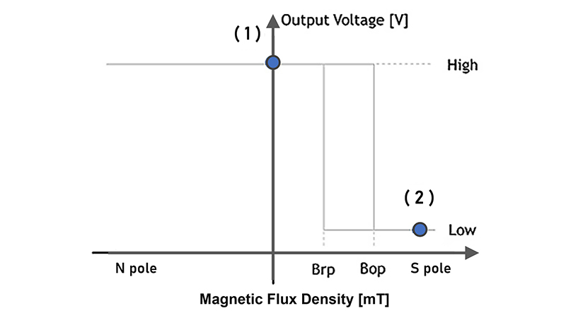 Figure 2b. Hall IC operation diagram
What makes AKM different ?
You may be surprised to find AKM's Hall sensors in such products as these! Hall sensors are used in familiar products such as air conditioners, washing machines, and smartphones. Here we will explain why AKM's Hall sensors are widely chosen by many people.
 Hall Sensors