-
Products

-
Applications
-
Support
-
About AKM
High-Sensitivity Hall Element
#06 Basic Knowledge of Magnetic Sensor
High-Sensitivity Hall Element Indium Arsenide (InAs)
Three types of Hall elements (ultra high-sensitivity, high-sensitivity, and low drift) were introduced in the section Types and Principles of Hall Elements.
This page explains some example applications of the high sensitivity Hall Element specifically.
Semiconductor Materials
(AKM's product name)
Indium Arsenide: InAs
(HQ series*) *Also containing Ga,Sb etc. as materials.
Features
InAs shows larger output voltage than the low drift Hall element (GaAs) and has more stable temperature characteristics than the ultra high-sensitivity Hall element (InSb) among the three Hall element types. (Refer to Types and Principles of Hall Elements)
This type of Hall element can also achieve more stable temperature characteristics in a constant voltage drive use case.
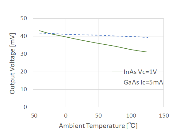 Figure 1. Output Voltage of InAs Hall Element (B=50mT)
Typical Applications
(1) Encoder
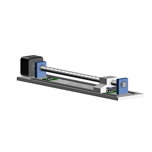
An encoder is a device that detects changes in the position of an object that rotates or moves linearly and outputs the position information as an electrical signal. A rotary type encoder that detects rotation is called a rotary encoder, and a linear type encoder that detects linear displacement is called a linear encoder.
It is used for precise motion and position control applications such as robot joints and industrial machine tools.
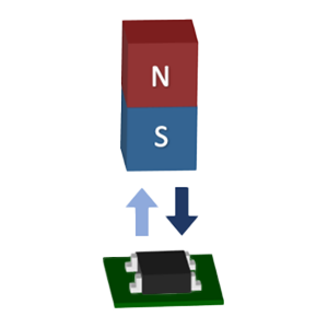
With a magnetic encoder, a magnet is attached to an object whose movement is to be detected, and its movement is detected by a Hall element. The following shows the detection principle of a magnetic rotary encoder (an encoder that detects rotation and angle).
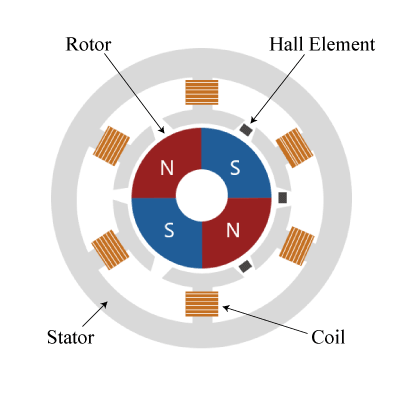
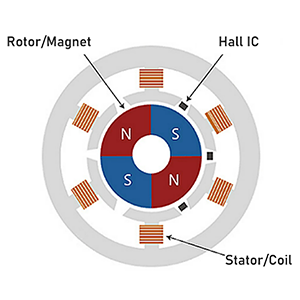
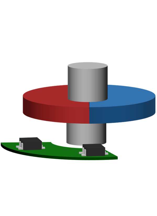 Figure 2a. Structure of Rotary Encoder using the Hall Element
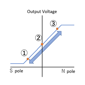
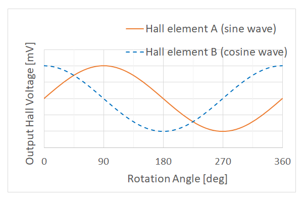 Figure 2b. Output Waves of Rotary Encoder using the Hall Element
The main components of the magnetic encoder are a circular (cylindrical or doughnut type) radially magnetized magnet and two Hall elements.
The two Hall elements are arranged so that they have a 90-degree positional relationship to a 360-degree rotational magnet in the magnetic encoder as shown in Figure 2a. When this magnet is rotated, sine and cosine wave output voltages are generated from the two Hall elements as shown in Figure 2b.
A rotational angle θ of the magnet can be calculated by calculating the arc tangent from output voltage of the two Hall elements using the formula tan θ = sin θ/cos θ.
(Since this calculation involves division, it also cancels the effects of temperature characteristics of both the magnet and the sensor. )
An optical encoder is a typical rotary encoder that uses angle detection. The magnetic encoder can detect even in dirt such as dust or oil and has more excellent environmental tolerance than the optical encoder.
(2) Autofocus mechanism for digital steel cameras
Various types of auto focus (AF) functions are used in the camera.
Of these, Figure 3. shows an example of how to focus with active AF.
First, the active AF measures the distance (L1) from a camera to the subject. *1
Then, based on the distance information (L1) and the focal length of the lens, you can calculate the position (L2) of the lens so that it can be imaged on the image pickup device and move it to focus.
*1 The distance from the camera to the subject (L1) is determined by using an infrared sensor or the like and detecting the rebound of infrared rays with the sensor.
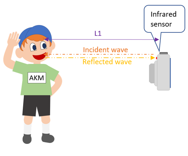 Figure 3a. How to measure the camera and subject with active AF
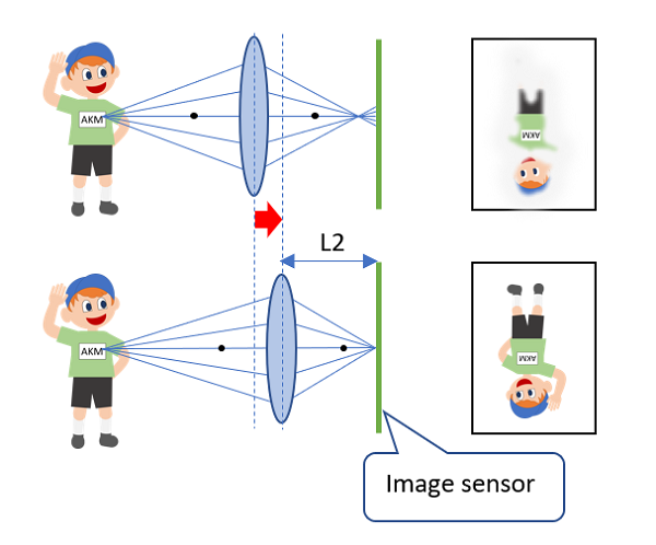 Figure 3b. How to image on the image sensor by driving the lens
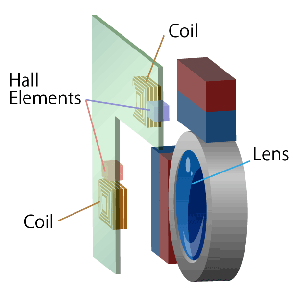
When the lens is moved so that the subject forms an image on the image pickup device, a Hall element is used to detect the amount of lens movement.
When moving the lens of a digital steel camera, its movement amount is about several mm.
There is a method described in "Low Drift Hall element" for the movement amount detection method, but this method is not suitable for the measurement of digital steel cameras with a lens movement distance of 1mm or more, because the stroke distance that can be accurately detected is approximately 1mm.
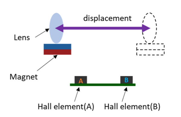
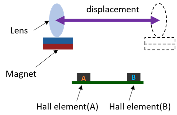 Figure 4. Configuration diagram for position detection using two Hall elements
For this reason, there is a method to extend the detection distance using two Hall elements A and B as shown in the figure below, for example.
The specific detecting method is to place the magnet in the direction where the poles of the magnet face each other with respect to the Hall element, and calculate the magnetic flux density difference (BA - BB) applied to each Hall element.
(In addition, the applied magnetic flux density difference (BA - BB) and the output voltage difference (VoutA - VoutB) of the respective Hall elements are equivalent in the movement amount detection.)
With this method, the output voltage can be obtained accurately with respect to the travel distance up to approximately 3mm.
(Magnet movement ∝ Magnetic flux density difference applied to the two Hall elements (BA - BB) ∝ Output voltage difference of the two Hall elements (VoutA - VoutB))
Furthermore, the temperature characteristics of the magnet and Hall element can be canceled by calculating the difference (VoutA - VoutB) ÷ sum (VoutA + VoutB), allowing for more accurate determination of the lens position. (Patent registered).
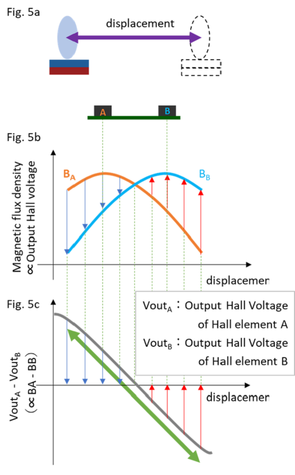
Figure 5a. Configuration diagram for position detection using two Hall elements
Figure 5b. Applied magnetic flux density of two Hall elements
Figure 5c. Output voltage difference between two Hall elements
◆TIPS why is an Indium Arsenide (InAs) Hall element used in the above application?
If you want to detect a short distance accurately (with an accuracy of 1/1000 for a distance of 1mm or less), you can detected with a single Hall element. Therefore, a GaAs Hall element with good temperature characteristics can be used for accurate detection.
(Refer to Figure 5a.)
However, if you want to detect a longer distance accurately (with an accuracy of 1/1000 for a distance of about 1mm to 3mm), you can extend the detection distance by calculating the operation of subtraction divided by summation using multiple Hall elements as described above.
Since this operation eliminates the effect of the temperature characteristics of the Hall element, InAs Hall element with a better signal-to-noise ratio improves the detection accuracy compared to the GaAs Hall element
(Refer to Figure 5b.)
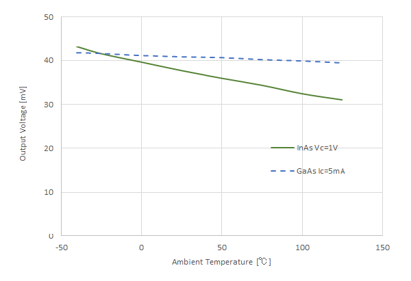 Figure 6a. Output Voltage of InAs Hall Element and GaAs Hall Element (B=50mT)
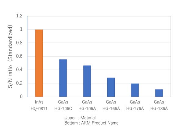 Figure 6b. InAs Hall Element and GaAs Hall Element S/N *InAs Hall Element S/N is set to 1
What makes AKM different ?
You may be surprised to find AKM's Hall sensors in such products as these! Hall sensors are used in familiar products such as air conditioners, washing machines, and smartphones. Here we will explain why AKM's Hall sensors are widely chosen by many people.
 Hall Sensors