-
Products

-
Applications
-
Support
-
About AKM
Ultra High-Sensitivity Hall Element
#04 Basic Knowledge of Magnetic Sensor
Ultra High-Sensitivity Hall Element (Indium Antimonide: InSb)
Three types of Hall elements (ultra high-sensitivity, high-sensitivity, and low drift) were introduced in the section Types and Principles of Hall Elements.
This page explains some example applications of the ultra high-sensitivity Hall Element specifically.
Semiconductor Materials
(AKM's product name)
Indium antimonide: InSb
(HW series)
Features
The ultra high-sensitivity Hall element is excellent at detecting changes in a magnetic field instantly due to it being the most sensitive among the three Hall element types. This type of Hall element can also achieve more stable temperature characteristics in a constant voltage drive use case than a constant current drive one would be able to.
(Refer to Types and Principles of Hall Elements)
Typical Applications
(1) DC Brushless Motor
A DC brushless motor is a high-efficiency and maintenance-free motor that rotates with direct current. This motor is used in fan motors for air conditioners, as well as main motors in other home appliances. Many DC motors include brushes as shown in Figure 1. Current flow is switched to the coils through the brushes which repeatedly make contact with the commutator (Rotor in Figure 1) as it rotates. This repeated physical contact between the brushes and the commutator causes the brushes to wear out.
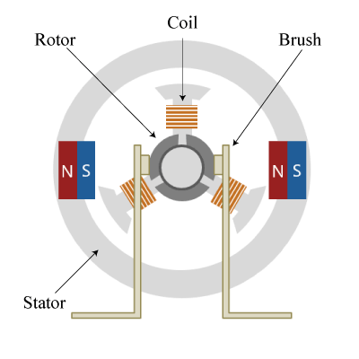 Figure 1. Diagram of brushed DC motor
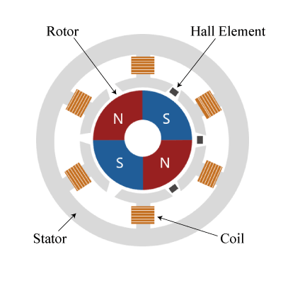
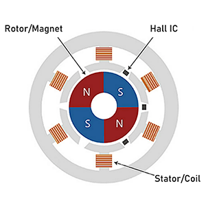
The brushless DC motor has a longer life due to its use of contactless sensor feedback instead of a switching commutator. The main components of brushless DC motor are magnets, Hall elements, and coils. As shown in Figure 2, magnets are placed on a rotating body at the center (rotor) and Hall elements attached to an outer fixed body (stator) detect the magnetic field from the rotor.
 Figure 2. Diagram of brushless DC motor with inner rotor
Based on the information of the magnetic field detected by each Hall element, current is varied to each coil to create an electromagnet. The strength and direction of the magnetic field generated by the electromagnets are controlled in a timely manner, and the rotor is rotated by the force of repulsion and attraction between the magnets of the rotor and the electromagnets of the coils.
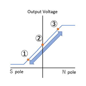
Since the Hall element itself has an offset voltage, the timing at which the Hall element detects the position of the magnet is affected.The top section of Figure 3 shows an example of the output voltage when the rotation of a magnet is detected by a Hall element with high sensitivity (blue line) and a Hall element with low sensitivity (yellow line). When there is no offset voltage, the switching of the output voltage (+/-) polarity normally corresponds to the switching of the magnet polarity (N/S). However, since an offset voltage does exist, timing gaps occur between the switching of output voltage polarities and the switching of the magnet polarities, as shown in Figure 3.
The bottom section of Figure 3 shows the detection timing diagram of how switching the north and south poles is detected relative to the switching of the polarity of output voltage of a Hall element with an offset voltage. When using a low sensitivity Hall element, a large deviation in duty ratio can be seen in the detection of north/south pole switching due to the effect of the offset voltage. However, a sensor with high-sensitivity, such as InSb, has a large output voltage compared to the offset voltage. Therefore, the deviation in duty ratio for detection of the north/south pole switching is small. Because of this, stable rotation of the magnet will improve motor rotation efficiency.
 Figure 3. Detection of motor's magnetic pole by a Hall element
(2) Closed-Loop Current Sensor
A magnetic current sensor detects the amount of current by measuring the magnetic field (i.e. magnetic flux density) generated around the current being measured. Closed-loop current sensors have many uses, such as in AC detectors of photovoltaic power conditioners. The magnetic flux density generated from the current is expressed by the following equation according to Biot-Savart's law.
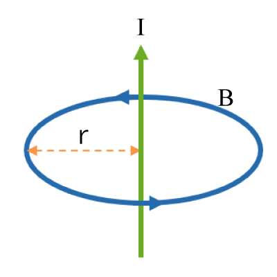 Figure 4. The Biot-Savart Law
B = μ0 /(2πr)× I
B: Magnetic Flux Density
μ0: Vacuum Permeability
r: Distance from Current Line
I: Current
As can be seen from the equation, the magnetic flux density is proportional to the current. The amount of current flowing through the conductor can be determined accurately by using the the Hall element to measure the magnetic field generated by the conductor. This method is different from the conventional method of measuring the voltage by inserting a shunt resistor (a small resistor for current-voltage conversion) directly into the current path being measured. It has the advantage that it can be measured without loss, since the current to be measured and the sensor signal are isolated from each other.
The closed-loop current sensor has the feature that it can accurately detect the amount of current by feedback control through sensing the magnetic field generated by the current. The main components of a closed-loop current sensor are the current conductor, a magnetic material that collects the magnetic field (called a "core"), a coil, and a Hall element. The core can be placed around a conductor with a Hall element in the gap of the core and then winding a coil around the core. When a current flows through the conductor, the generated magnetic field is collected into the core and applied to the Hall element in the gap of the core.
A feedback circuit is created by supplying a current to the coil wound around the core, such that a magnetic field is created with reverse phase with respect to the magnetic field generated from the input current. The coil current is generated based on the output voltage of the Hall element and compensates so that the output voltage of the Hall element is always 0V. The amount of current flowing through the input conductor can be calculated from the amount of current flowing through the coil. Since the closed-loop current sensor detects whether the output voltage of the Hall device is at 0V or not, the amount of current flow can be detected with high accuracy using highly sensitive InSb.
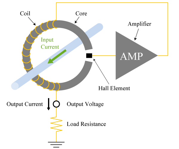 Figure 5. Closed-Loop Current Sensor
What makes AKM different ?
You may be surprised to find AKM's Hall sensors in such products as these! Hall sensors are used in familiar products such as air conditioners, washing machines, and smartphones. Here we will explain why AKM's Hall sensors are widely chosen by many people.
 Hall Sensors