-
Products

-
Applications
-
Support
-
About AKM
Linear Hall IC
#10 Basic Knowledge of Magnetic Sensor
Linear Hall ICs are sensors that provide rail-to-rail analog output and are used in white goods and industrial equipment, just like Hall ICs, because they can be easily processed by the subsequent microcontroller.
Linear Hall ICs have an analog output, so they have the advantage of being able to detect positions more accurately than Hall ICs with digital output. This page explains the principles and applications of linear Hall ICs.
Principle of linear Hall IC
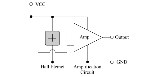
A linear Hall IC is a sensor that amplifies the output voltage of a built-in Hall element using a subsequent processing IC and outputs it linearly in the range of 0 to Vcc (Figure 1). Linear Hall ICs with various sensitivities are available depending on the amplification factor of this particular IC.
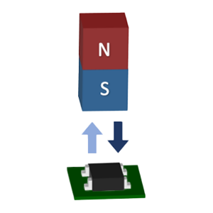
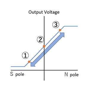
When no magnetic field is applied, the output is Vcc/2. The output increases or decreases (0 to Vcc) when the N pole or S pole magnetic field is applied. If the magnetic field is applied outside the specification range, the output will be saturated.
Therefore, it is recommended to select a linear Hall IC with the optimal sensitivity according to the magnetic field range to be measured for effective use of the output range for detection.
Like Hall ICs, the output voltage range of the linear Hall ICs is determined by the power supply, making it easier for the subsequent microcontroller to accept the output voltage range.
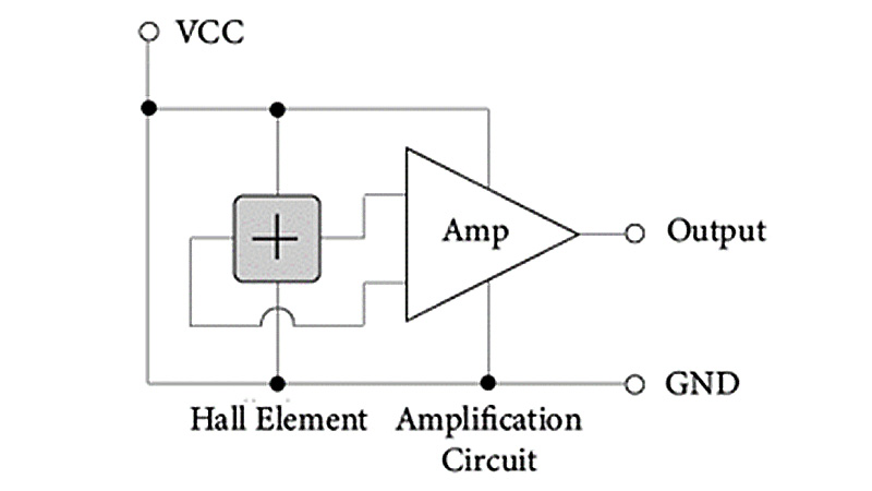 Figure 1. Operating circuit (reference diagram)
Typical application examples
(1) Fuel gauge/liquid level gauge sensor capable of detecting liquid level
Fuel gauge and liquid level gauge sensors detect the remaining amount of liquid fuel, that of water in a storage tank, as well as the amount of water stored. Since the sensor can detect the liquid level without contact from outside the container and without mechanical contact and electric circuits can be installed outside the tank, it has the advantage of being usable even with flammable liquids. It is usually used to detect the upper limit (full) or lower limit (empty) of the liquid level in a tank. The main components for liquid level detection are magnets, linear Hall ICs, and floats.
When there is sufficient liquid in the tank, as shown in (1) in Figure 2, a S pole magnetic field is applied, and the output of the linear Hall IC will be around 0 V.
As the liquid level falls, the S pole magnetic field that is applied to the linear Hall IC decreases, and the output gradually increases. As shown in (2) in Figure 2, when the boundary between the S and N poles of the magnet reaches the front of the linear Hall IC, the magnetic flux density in the sensor's magnetically sensitive direction (left and right directions in Figure 2 (1) - (3) ) becomes 0 mT.. Therefore, the output of the linear Hall IC becomes the midpoint voltage (For example, when the power supply voltage is 5 V, it will be 2.5 V).
As the water level drops further, the N pole magnetic field is applied little by little, so the output of the linear Hall IC gradually increases. When the liquid runs out, as shown in (3) in Figure 2, a large N pole magnetic field is applied to the linear Hall IC, thereby outputting a voltage that is about the same as the power supply voltage.
Unlike a switch-type Hall IC, a linear Hall IC can detect not only the lower limit of the liquid level position but also the position of liquid level up to the lower limit because of its analog output. Additionally, the detection range can be expanded by using multiple magnets and sensors. However, it is necessary to examine the use comprehensively including the specified magnetic field range, magnet size, and distance between the magnetic and the linear Hall IC.
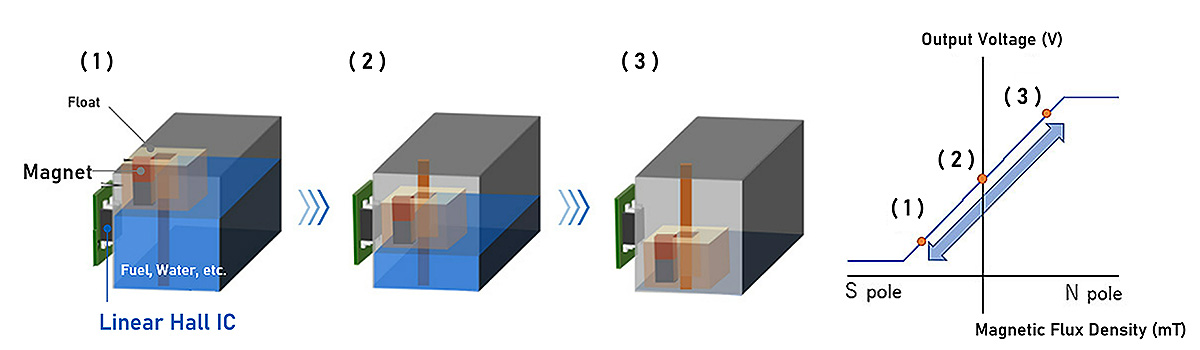 Figure 2. Example of remaining amount detected by liquid level gauge and diagram of the linear Hall IC
(2) Input lever for operation
The control input lever is a stick-type analog interface that is normally used to operate games, radio controls, and equipment.
The main components of the control input lever are the lever, hinge, circular magnet, and linear Hall IC.
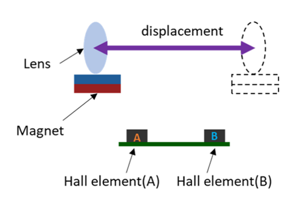
Linear output can be obtained within a lever angle of approximately ±30°in the follwing configuration. A linear Hall IC is placed directly below the hinge that secures the lever, then, a circular magnet is installed so that the border between the S and N poles is directrly above the linear Hall IC when the lever is in the middle of its stroke, as shown in (2) in Figure 3.
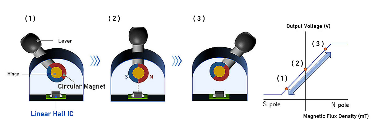 Figure 3. Example of input lever for operation and diagram of linear Hall IC
(3) Open loop current sensor
A magnetic current sensor detects the amount of current by measuring the magnetic flux density that is generated around the current line being measured (Figure 4).
The configuration is designed by simply replacing the Hall element in "#05 Low Drift Hall Element (2) Open Loop Current Sensor" with a linear Hall IC. The advantage of using a linear Hall IC is that it does not require an amplifier circuit following the Hall element.
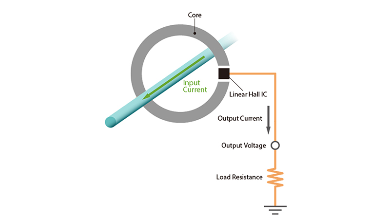 Figure 4. Principle diagram of current sensor using linear Hall IC
What makes AKM different ?
You may be surprised to find AKM's Hall sensors in such products as these! Hall sensors are used in familiar products such as air conditioners, washing machines, and smartphones. Here we will explain why AKM's Hall sensors are widely chosen by many people.
 Hall Sensors