
CQ2 Series
-
[Q0155]
・How much current can be flown in CQ-2 series?
-
A.
・It is possible to flow current of up to 50Arms.
Was it helpful?YesNoThank you We will reflect your opinion on the improvement of the web content.
-
[Q0156]
・How much pulse current can be flown in CQ-2 series?
-
A.
・It has been confirmed by an experiment in AKM labo that CQ-2 series did not break at a pulse current of 500A, 100us.
Was it helpful?YesNoThank you We will reflect your opinion on the improvement of the web content.
-
[Q0157]
・What is the difference of maximum primary current and linear sensing range?
-
A.
・Maximum primary current indicates the current value which can be applied for a long time in current sensor and depends on the cross-sectional area of the primary conductor. CQ-2 series can be damaged when they have been used for a long time over the maximum effective current value. If current flows at a short period within msec, such as an over current, CQ-2 series is not damaged.
Linear sensing range is a current range where linear output of the current sensor is guaranteed. Output will be saturated when the current value exceeds the linear sensing range, and will return to normal output when the current value returns within the linear sensing range.
Was it helpful?YesNoThank you We will reflect your opinion on the improvement of the web content.
-
[Q0158]
・What is the difference between the lineups of CQ-2 series?
-
A.
・A table showing the differences between the products is available on the CQ2 series page.
Was it helpful?YesNoThank you We will reflect your opinion on the improvement of the web content.
-
[Q0159]
・What kind of packages does AKM use?
-
A.
・CQ-2 series use AKM's original package called AI-Shell which has a simple structure with case, the Hall sensor, magnetic core, and primary conductor.
Was it helpful?YesNoThank you We will reflect your opinion on the improvement of the web content.
-
[Q0160]
・Can CQ-2 series detect unipolar current? (e.x. current detection of 0 to 40A)
-
A.
・CQ-2 series can detect unipolar current. Moreover, there are product lineups which are specialized in unipolar detection such as CZ-372x. Please select the product which is most suited to your requirements.
Was it helpful?YesNoThank you We will reflect your opinion on the improvement of the web content.
-
[Q0161]
・How small is a current resolution?
-
A.
・The output voltage noise of the CQ2 series is 1.2mVrms.
By dividing this value by the current sensitivity of each product, the input current equivalent noise is obtained.
Table 1: Input current equivalent noise Was it helpful?YesNoThank you We will reflect your opinion on the improvement of the web content.
-
[Q0162]
・What safety standards CQ-2 series have?
-
A.
・CQ-223x and CQ-233x series have been certified with IEC/UL-62368-1 and UL-508 by the international certification association. The certification documents are available on the CQ2 series page.
Was it helpful?YesNoThank you We will reflect your opinion on the improvement of the web content.
-
[Q0163]
・Are CQ-2 series compliant with halogen-free/RoHS?
-
A.
・CQ-2 series are compliant with halogen-free/RoHS.
Was it helpful?YesNoThank you We will reflect your opinion on the improvement of the web content.
-
[Q0164]
・Is it possible to sense both DC current and AC current?
-
A.
・They can sense both DC current and AC current.
Was it helpful?YesNoThank you We will reflect your opinion on the improvement of the web content.
-
[Q0165]
・What does "ratiometric" mean?
-
A.
・Ratiometric output means the output characteristic which varies in proportional to the power supply voltage. In the case that the output of a current sensor is captured by an A/D converter, ratiometric output can reduce the A/D conversion error due to variations of the reference voltage of A/D converter, by maiking reference voltage from the same power source as the current sensor. Both sensitivity and output voltage of CQ2 series have the ratiometric characteristics.
Recommended circuit is shown in Fig 1.
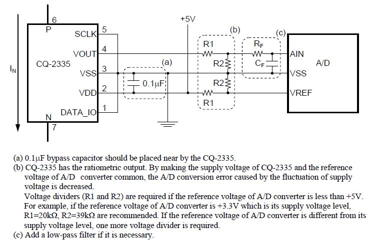
Fig.1. Recommended external circuits of CQ-2 series Was it helpful?YesNoThank you We will reflect your opinion on the improvement of the web content.
-
[Q0166]
・What is the ESD tolerance?
-
A.
・CQ-2 series have the ESD tolerance which is more than 2000V by human body model and more than 200V by machine model.
Was it helpful?YesNoThank you We will reflect your opinion on the improvement of the web content.
-
[Q0167]
・Do CQ-2 series support the Pb-free product?
-
A.
・CQ-2 series are compliant with Pb-free.
Was it helpful?YesNoThank you We will reflect your opinion on the improvement of the web content.
-
[Q0168]
・What happens if a load capacitance over 100pF is applied to CQ-2 series?
-
A.
・CQ-2 series do not output the correct value because of the oscillation of output. It is no problem to add a low-pass filter.
Was it helpful?YesNoThank you We will reflect your opinion on the improvement of the web content.
-
[Q0169]
・What happens if a load current over +/-0.5mA is applied to CQ-2 series?
-
A.
・CQ-2 series do not output the correct value because output of CQ-2 series cannot drive the load.
Was it helpful?YesNoThank you We will reflect your opinion on the improvement of the web content.
-
[Q0251]
・How should the board be soldered?
-
A.
・Although the reference conditions are shown as follows, please apply them only after careful examination and confirmation by the customer.

1. Dipping (dipping entire element)
 When dipping is employed, processing in the condition within the temperature load shown in Figure 2 is recommended. Solder dipping should only be performed once. For CQ-Series, take care to avoid dipping a magnetic core.
2. Hand soldering (using soldering iron)
 Solder under thermal load at 260°C for less than 10 seconds, or 350°C for less than 3 seconds, without touching the body of the element. Hand soldering should be completed twice.
3. Reflow
 When reflow is employed, processing within the temperature profile shown in Figure 3 is recommended. Reflow soldering should be completed twice.
4. Solder flux
 Colophonium system solder flux is recommended. Use of an organic acid system, inorganic acid system or water-soluble fluxes should be avoided.
Figure 2: Solder dipping condition 
Figure 3: Solder reflow condition Was it helpful?YesNoThank you We will reflect your opinion on the improvement of the web content.
-
[Q0252]
・Is there the recommended land pattern?
-
A.
・Yes. The recommended land pattern is shown in the figure 4.
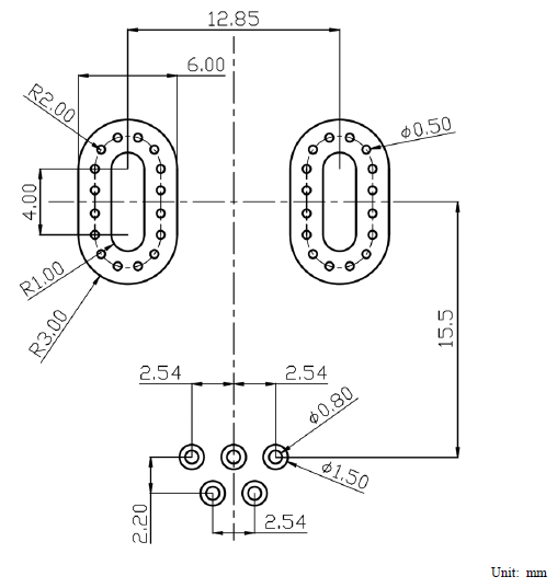
Figure 4. Recommended Land Pattern of CQ-223x Was it helpful?YesNoThank you We will reflect your opinion on the improvement of the web content.
-
[Q0253]
・Is gerber file of the evaluation board given?
-
A.
・Yes, you can download it from the CQ2 series page.
Was it helpful?YesNoThank you We will reflect your opinion on the improvement of the web content.
-
[Q0254]
・How is the die temperature taken?
-
A.
・It can be estimated by using the forward characteristics of the diode inside the IC, please refer to the technical content "Estimated method of the CQ-2 series IC internal temperature" on the CQ2 series page.
Was it helpful?YesNoThank you We will reflect your opinion on the improvement of the web content.
-
[Q0256]
・What is the primary conductor made from?
-
A.
・The primary conductor is made from copper.
Was it helpful?YesNoThank you We will reflect your opinion on the improvement of the web content.
-
[Q0262]
・How much is the temperature drift of the primary conductor resistance of CQ2 series?
-
A.
・The primary conductor resistance of the CQ2 series has a temperature characteristic as shown in Figure 5.
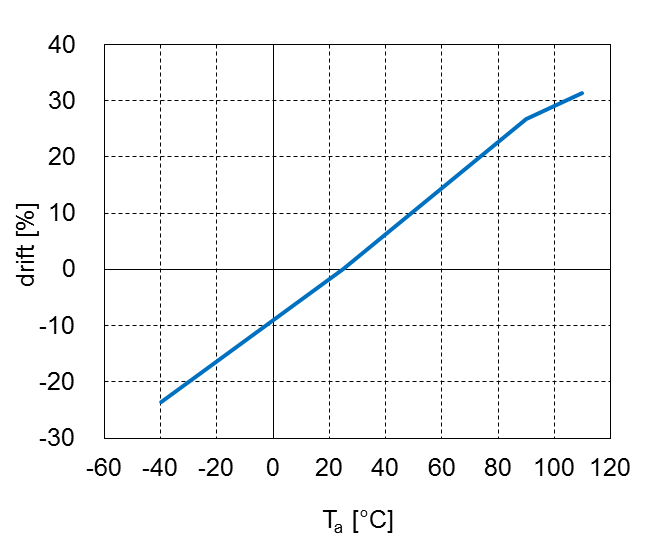
Figure 5. The temperature drift of the primary conductor resistance to the resistance at 25°C Was it helpful?YesNoThank you We will reflect your opinion on the improvement of the web content.
-
[Q0263]
・Is the device used more than the rating isolation voltage of the data-sheet?
-
A.
・The device should be used with a recommended condition.
Was it helpful?YesNoThank you We will reflect your opinion on the improvement of the web content.
-
[Q0264]
・What is the response time?
-
A.
・Response time is 1μs. (In the case of load capacity of 100pF)
Was it helpful?YesNoThank you We will reflect your opinion on the improvement of the web content.
-
[Q0265]
・How many is the CTI of the package?
-
A.
・CQ-223x has Anti-tracking resistance of CTI 150.
Was it helpful?YesNoThank you We will reflect your opinion on the improvement of the web content.
-
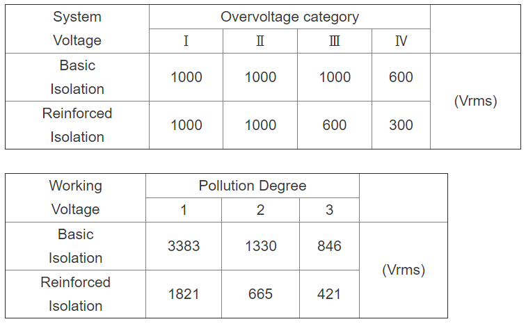
[Q0266]
・How much is the isolation voltage of CQ-2 series?
-
A.
・CQ-2 series can be used under the following conditions.
 Was it helpful?YesNoThank you We will reflect your opinion on the improvement of the web content.
-
[Q0267]
・How many is constant number of R and C?
-
A.
・Add a low-pass filter (R and C) if it is necessary.
Was it helpful?YesNoThank you We will reflect your opinion on the improvement of the web content.
-
[Q0268]
・Is the data communication pin used?
-
A.
・The data communication pin is not used. The product is adjusted before shipment in AKM. Please contact us because there is possibility to be able to accommodate depending on volume.
Was it helpful?YesNoThank you We will reflect your opinion on the improvement of the web content.
-
[Q0269]
・What are materials of the cores?
-
A.
・Ferite core is used in CQ223x.
Was it helpful?YesNoThank you We will reflect your opinion on the improvement of the web content.
-
[Q0291]
・How soon after power-on will a valid signal be available from the CQ233x?
-
A.
・The power-on time is 21us for both Iin=0A and Iin=21A cases. However, we recommend a 3X to 5X safety margin to account for power-on time variation over process and temperature ranges.
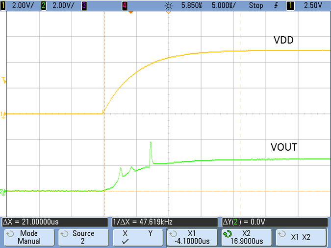
Figure 6. Startup of CQ233x with 0 A applied, then a VDD step from 0 to 5 V. 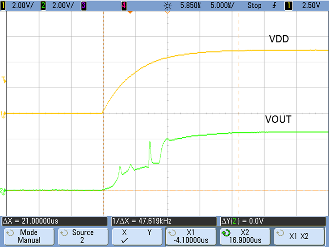
Figure 7. Startup of CQ233x with 21 A applied, then a VDD step from 0 to 5 V. Was it helpful?YesNoThank you We will reflect your opinion on the improvement of the web content.
-
[Q0292]
・How will capacitive coupling between the primary conductor in the CQ2 series and the Hall sensor affect the sensor output?
-
A.
・The current path noise rejection test is conducted by injecting a high-frequency sinusoidal frequency onto the primary conductor. The CQ2 series exhibit a high level of current path noise rejection as table 2 reveals. In addition, figure 8 indicates performance as a function of frequency.
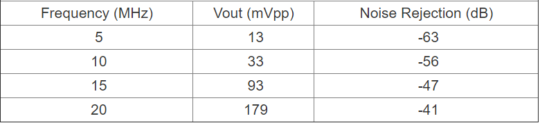
Table 2. Typical Capacitive Coupling of 20 Vp-p Signal on the Sensed Current Path 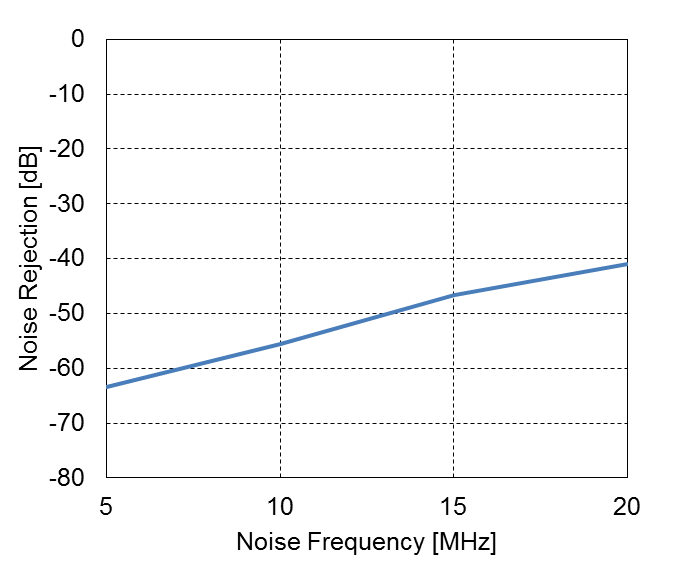
Figure 8. CQ233x noise rejection versus noise frequency Was it helpful?YesNoThank you We will reflect your opinion on the improvement of the web content.
-
[Q0293]
・What is the frequency response of CQ2 series?
-
A.
・The graph in figure 9 shows the results of the typical frequency response of the CQ2 series. The plot on the top is the amplitude response and the plot on the bottom is the phase response.
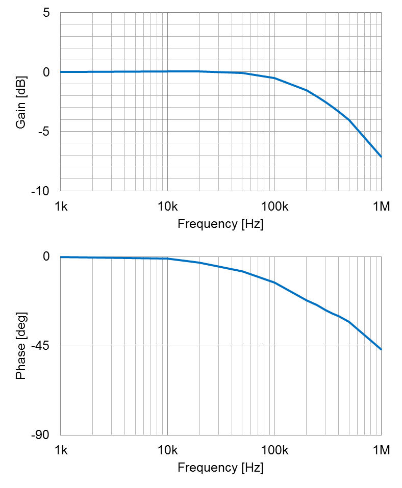
Figure 9. Frequency Response of the CQ2 Was it helpful?YesNoThank you We will reflect your opinion on the improvement of the web content.
-
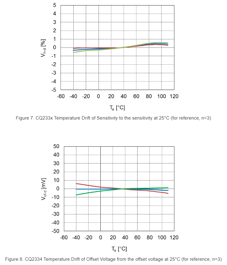
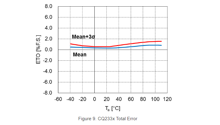
[Q0294]
・What does the characterization data look like at the sensor IC full linear sensing range?
-
A.
・Please see the graphs below for Temperature Drift of Sensitivity in figure 7, Temperature Drift of Offset Voltage in figure 8 and Total Error in figure 9.
 Was it helpful?YesNoThank you We will reflect your opinion on the improvement of the web content.
-
[Q0605]
・Are there any precautions to be taken regarding withstanding voltage?
-
A.
・1. Please use sensors within the maximum rating and under the recommended operating conditions. Sensors can be destroyed if they are used over the maximum rating. In particular, please take care to avoid applying high voltage directly on the element.
2. Sensors have a polarity on the package pins. Please take care to avoid reverse connection.
3. Please take measures to protect against surge voltage and static charges in storage, handling, and mounting on a circuit.
4. Use sensors in a manner that does not allow sensors to touch the moving materials such as motors.
Was it helpful?YesNoThank you We will reflect your opinion on the improvement of the web content.
-
[Q0606]
・Is there anything I need to know about the storage environment?
-
A.
・The product should be stored at 30°C and 85%RH or less, away from direct sunlight.
(Please follow the conditions of MSL1)
Was it helpful?YesNoThank you We will reflect your opinion on the improvement of the web content.
-
[Q0607]
・Is there anything I should know about long-term storage?
-
A.
・If the elements are stored for an extended time (two years or more) under the general storage conditions for semiconductors, the soldering characteristics of the lead terminal and the electrical characteristics could deteriorate; therefore, only use such elements after verifying their soldering and electrical characteristics, etc..
We recommend long-term storage in a nitrogen atmosphere. The lead of the element will be oxidized by the oxygen in the atmosphere, and the soldering characteristics will deteriorate if the elements are stored in a normal atmosphere.
Was it helpful?YesNoThank you We will reflect your opinion on the improvement of the web content.
-
[Q0608]
・Are there any precautions to be taken when handling the product?
-
A.
・As Hall ICs and current sensors contain gallium arsenide or indium arsenide, observe the following procedures for safety.
1) Handling of Hall ICs and current sensors
- Do not alter the form of this product into a gas, powder, liquid, through burning, crushing, or chemical processing.
- These products should not be used under the environment with corrosive gas including chlorine or sulfur.
- These products are lead (Pb) free. All leads are plated with 100% tin. Do not store this product alone in high temperature and high humidity environment. Moreover, this product should be mounted on substrate within six months after delivery.
- These products are damaged when it is used on the following conditions:
- Supply voltage is applied in the opposite way.
- Overvoltage which is larger than the value indicated in the specification.
- These products are will be damaged if it is used for a long time with the current (effective current) which exceeds the current rating. Careful attention must be paid so that maximum effective current is smaller than current rating.
- Since magnetic cores are fragile parts, do not use the fallen products.
- The characteristic can change by the influences of nearby current and magnetic field. Please make sure of the mounting position.
Was it helpful?YesNoThank you We will reflect your opinion on the improvement of the web content.
-
[Q0609]
・How can I dispose of it?
-
A.
・Observe laws and company regulations when discarding Hall ICs and current sensors.
Was it helpful?YesNoThank you We will reflect your opinion on the improvement of the web content.