
CQ330x Series
-
[Q0304]
・Is it possible to sense both DC current and AC current?
-
A.
・It is possible to sense both DC current and AC current.
Was it helpful?YesNoThank you We will reflect your opinion on the improvement of the web content.
-
[Q0305]
・What is the difference between "maximum primary current" and "linear sensing range"?
-
A.
・Maximum primary current indicates the current value which can be flown for a long time in a current sensor and depends on the cross-sectional area of the primary conductor.
CQ-330x/CQ-320x  can be damaged when it has been used for a long time over the maximum effective current value. If current flows at a short period within msec order, such as an over current, CQ-330x/CQ-320x  will not be damaged.
Was it helpful?YesNoThank you We will reflect your opinion on the improvement of the web content.
-
[Q0306]
・How much pulse current can be flown in CQ-330x/CQ-320x?
-
A.
・It has been confirmed by an experiment in AKM labo that CQ-330x/CQ-320x did not break under pulse current conditions of Table 1.
Table 1. Sustainable Pulse Current Condition Was it helpful?YesNoThank you We will reflect your opinion on the improvement of the web content.
-
[Q0307]
・How much rms current can be flown in CQ-330x/CQ-320x?
-
A.
・It is possible to flow current up to 20Arms(maximum primary current) in CQ-330x/CQ-320x.
Was it helpful?YesNoThank you We will reflect your opinion on the improvement of the web content.
-
[Q0308]
・Can CQ-330x/CQ-320x detect only unipolar current?
 (ex. Current detection of 0 to 21A)
-
A.
・CQ-330x/CQ-320x detects both bipolar and unipolar current.
CQ-330x/CQ-320x series  bipolar and unipolar brand.
Please refer to 'Selection Guide' and 'Lineup'.

CQ-330x(x shows the brand as below)
Unipolar::x=B,E,F,J
Bypolar:x=0,1,2,3,A,G,H

CQ-320x(x shows the brand as below)
Unipolar:x=B
Bypolar:x=0,1,2,3,4,A
Was it helpful?YesNoThank you We will reflect your opinion on the improvement of the web content.
-
[Q0309]
・How much current resolution can the CQ-330x/CQ-320x achieve?
-
A.
・The current resolution is determined by its output noise voltage.
The current resolution can be increased by applying a noise filtering circuit.

(a) 0.1μF bypass capacitor should be placed close to VDD and VSS pins of CQ-330x/CQ-320x.
(b) Add a low-pass filter if it is necessary.
The RF、CF values should be fixed in consideration of load conditions.
Figure 1. External Circuits Example Was it helpful?YesNoThank you We will reflect your opinion on the improvement of the web content.
-
[Q0310]
・How big is the production tolerance in primary conductor resistance?
-
A.
・The primary conductor resistance temperature drift of CQ-330x/CQ-320x is shown in See Figure 2.
Figure 2. CQ-330x/CQ-320x Temperature Drift of the Primary Conductor Resistance (normalized at 25℃) Was it helpful?YesNoThank you We will reflect your opinion on the improvement of the web content.
-
[Q0311]
・What does the ratiometric property mean?
-
A.
・The CQ-330x/CQ-320x has a ratiometric output. This means that the output of the current sensor changes proportionally to the supply power voltage. A ratiometric output is suitable for applications where the output is converted to digital using an A/D converter and where fluctuation of the power supply voltage causes reference error of the A/D converter.
[Q0470] External Circuit Case 1) shows an example of the external circuit where a 5V A/D converter is connected.  [Q0470] External Circuit Case 2) shows the case where a 3.3V A/D converter is used. The supply voltage of the CQ-330x/CQ-320x and the reference voltage of the A/D converter fluctuate at the same ratio. This will avoid the effects of the fluctuation of the power supply to the A/D converter output.
Figure 3 Shows the output voltage of CQ-3302 (Sensitivity Vh=100mV/A) and CQ-3202 (Sensitivity Vh=62.5mV/A) as an example ratiometric output.
Figure 3. Output voltage of the CQ-330x/CQ-320x vs Input Current with different VDD. Was it helpful?YesNoThank you We will reflect your opinion on the improvement of the web content.
-
[Q0312]
・How fast is the power-on time ?
-
A.
・The power-on time is 21 μs.
We recommend a 3X to 5X safety margin to account for power-on time variation over process and temperature ranges.
Was it helpful?YesNoThank you We will reflect your opinion on the improvement of the web content.
-
[Q0313]
・How about the frequency characteristic?
-
A.
・Figure 4 shows the typical frequency characteristic of the CQ-330x/CQ-320x.
(Top : amplitude, Bottom : phase delay)
Figure 4. Frequency Response of the CQ-330x/CQ-320x Was it helpful?YesNoThank you We will reflect your opinion on the improvement of the web content.
-
[Q0314]
・What is the response time?
-
A.
・Response time is TYP 0.5μs.(In the case of load capacity of 100pF)
Figure 5 shows the rise response and fall response waveform of CQ-330x .Figure 6 shows the rise response and fall response waveform of CQ-320x
Figure 5. CQ-330H Rise response waveform (left), fall response waveform(right). 
Figure 6. CQ-3204 Rise response waveform (left), fall response waveform(right). Was it helpful?YesNoThank you We will reflect your opinion on the improvement of the web content.
-
[Q0315]
・What is the response time of VOUT from deep saturation?
-
A.
・The VOUT response time of CQ-3300 from deep saturation was less than 1 µs by AKM measurement. Figure 6 shows the transient response waveform of CQ-3300.
Figure 6 The CQ-3300 Transient Response Waveform from the VOUT Deep Saturation. Was it helpful?YesNoThank you We will reflect your opinion on the improvement of the web content.
-
[Q0316]
・What happens if a load capacitance over 100pF is inserted to the CQ-330x/CQ-320x VOUT?
-
A.
・CQ-330x/CQ-320x does not output the correct value because of the oscillation of output.
Was it helpful?YesNoThank you We will reflect your opinion on the improvement of the web content.
-
[Q0317]
・What happens if a load current over +/-0.5mA is applied to CQ-330x/CQ-320x VOUT?
-
A.
・The CQ-330x/CQ-320x does not output the correct value.
Please use under the recommended operating conditions.
Was it helpful?YesNoThank you We will reflect your opinion on the improvement of the web content.
-
[Q0318]
・What safety standards CQ-330x/CQ-320x have?
-
A.
・CQ-330x/CQ-320x have been certified withUL508 and IEC/UL-62368 by the international certification association.

・UL 508 – Industrial Control Equipment – Edition 17.
(File No. E353882)
・IEC/UL62368-1 -Audio/video, Information and Communication Technology Equipment- 2nd Edition(File No.E359197)
・CAN/CSA C22.2 No.62368-1-14 -Audio/video, Information and Communication Technology Equipment- 2nd Ed,(File No.E359197)
Was it helpful?YesNoThank you We will reflect your opinion on the improvement of the web content.
-
[Q0319]
・What is the clearance distance and the creepage distance?
-
A.
・The clearance distance and the creepage distance are both over 5.0mm.
Was it helpful?YesNoThank you We will reflect your opinion on the improvement of the web content.
-
[Q0320]
・How big is the CTI value of the CQ-330x/CQ-320x package material?
-
A.
・The Comparative Tracking Index (CTI) of the CQ-330x/CQ-320x package resin is 600V. The Material Group is I.
Was it helpful?YesNoThank you We will reflect your opinion on the improvement of the web content.
-
[Q0321]
・How big is the working voltage of CQ-330x/CQ-320x?
-
A.
・CQ-330x/CQ-320x can be used under the following conditions.
 Was it helpful?YesNoThank you We will reflect your opinion on the improvement of the web content.
-
[Q0322]
・Is it allowable to use this device over the rating isolation voltage in the data-sheet?
-
A.
・No, it cannot be used under the conditions that exceed the isolation voltage. We cannot guarantee characteristics of the CQ-330x/CQ-320x.
 The device should be used under the recommended condition.
Was it helpful?YesNoThank you We will reflect your opinion on the improvement of the web content.
-
[Q0323]
・How big is the voltage noise rejection ratio?
-
A.
・The Voltage Noise Rejection Ratio of the Primary Conductor was calculated by measuring the output while a high frequency sine wave voltage was applied as the input noise to the primary conductor.
Table 3 shows the CQ-330x/CQ-320x series having a strong voltage noise rejection ratio.
Figure 7 shows the frequency dependency of the voltage noise rejection ratio.
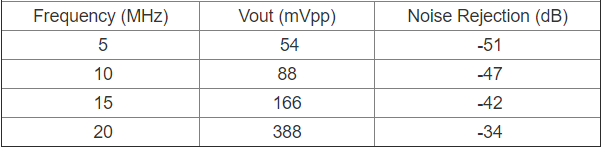
Table 3. Voltage Noise Rejection Ratio when high frequency sine wave voltage 
Figure 7. CQ-330x/CQ-320x Noise Frequency vs Voltage Noise Rejection Ratio Was it helpful?YesNoThank you We will reflect your opinion on the improvement of the web content.
-
[Q0324]
・How do I connect thermal radiation pin (TAB1, TAB2) ?
-
A.
・Please layout the thermal radiation pattern to be larger, while ensuring the necessary creepage distance and clearance distance between the primary side.
The recommended circuit shown in Figure 8  (Please refer to [Q0327]).
Figure 8 CQ-330x Recommended Circuit Diagram Was it helpful?YesNoThank you We will reflect your opinion on the improvement of the web content.
-
[Q0325]
・How do I decide the time constant value RC ?
-
A.
・Please decide the time constant value considering the requirement of output resolution and response time. (Please refer to [Q0309]).
Was it helpful?YesNoThank you We will reflect your opinion on the improvement of the web content.
-
[Q0326]
・How should I solder the CQ-330x/CQ-320x to the board?
-
A.
・Please refer to "Soldering condition" described in Important notices page.
Was it helpful?YesNoThank you We will reflect your opinion on the improvement of the web content.
-
[Q0327]
・Can I get the recommended land pattern?
-
A.
・Yes. The recommended land pattern is shown in Figure 9.
Figure 9. CQ-330x/CQ-320x recommended land pattern Was it helpful?YesNoThank you We will reflect your opinion on the improvement of the web content.
-
[Q0328]
・Can I get the board layout guidelines of CQ-330x/CQ-320x?
-
A.
・Please see the application notes (2. Board Design Guidelines) here.
Was it helpful?YesNoThank you We will reflect your opinion on the improvement of the web content.
-
[Q0329]
・Is gerber file of the evaluation board provided?
-
A.
・Yes, please download from: Gerber Files.
Was it helpful?YesNoThank you We will reflect your opinion on the improvement of the web content.
-
[Q0330]
・What is the ESD tolerance?
-
A.
・CQ-330x have the ESD tolerance which is more than 2000V by human body model (HBM) and more than 200V by machine model (MM).
Was it helpful?YesNoThank you We will reflect your opinion on the improvement of the web content.
-
[Q0331]
・What should I take care of the other current lines(stray magnetic field)?
-
A.
・CQ-330x/CQ-320x can be detected the primary current by detecting the magnetic flux density of primary current. Therefore, CQ-330x/CQ-320x is affected by external magnetic field, and this will appear as output error. In this section, we show about the situation affected by nearby current lines.

Figure 10 defines the distance from nearby current lines.
Figure 11 shows the relationship between “output error” and “distance A/B”.

Example:
In case of the nearby current is 20A and its output error keep less than 400mA,
CQ-330x/CQ-320x keeps the clearance more than 6mm (Distance A) and 5mm (Distance B).
*Distance B is not only defined as the line on the left of CQ-330x/CQ-320x package but also the line on the right ofCQ-330x/CQ-320x package.
Figure 10. The definition of Distance 
Figure 11. The relationship between output error and distance Was it helpful?YesNoThank you We will reflect your opinion on the improvement of the web content.
-
[Q0332]
・Can I get a way to estimate the temperature inside CQ-330x/CQ-320x?
-
A.
・It is possible to estimate the internal temperature measuring the diode characteristics of the IC (Technical Resource: Estimated method of the CQ-3 series IC internal temperature). Please ensure the junction temperature (Tj) is kept lower than 125℃.
Was it helpful?YesNoThank you We will reflect your opinion on the improvement of the web content.
-
[Q0333]
・Is CQ-330x/CQ-320x halogen-free/RoHS?
-
A.
・CQ-330x/CQ-320x is halogen-free/RoHS.
Was it helpful?YesNoThank you We will reflect your opinion on the improvement of the web content.
-
[Q0334]
・Is  CQ-330x/CQ-320x Pb-free?
-
A.
・CQ-330x/CQ-320x is Pb-free.
Was it helpful?YesNoThank you We will reflect your opinion on the improvement of the web content.
-
[Q0335]
・What is the primary conductor made of?
-
A.
・The primary conductor is made of copper.
Was it helpful?YesNoThank you We will reflect your opinion on the improvement of the web content.
-
[Q0336]
・Is it possible to use the internal EEPROM?
-
A.
・Sorry, internal EEPROM is not available.
 Products will be shipped after the adjustment of EEPROM at factory test.
Was it helpful?YesNoThank you We will reflect your opinion on the improvement of the web content.
-
[Q0337]
・Is it possible to order the customized products?
-
A.
・It is possible to provide the customized product, depending on quantity conditions and your requirement. Please contact us.
Was it helpful?YesNoThank you We will reflect your opinion on the improvement of the web content.
-
[Q0465]
・How big is the production tolerance in primary conductor resistance?
-
A.
・The production tolerance in primary conductor resistance is from 1.2 to 2.1mΩ (reference) at 25°C.
Was it helpful?YesNoThank you We will reflect your opinion on the improvement of the web content.
-
[Q0466]
・How big is the primary conductor inductance?
-
A.
・The primary conductor inductance is about 2.7nH (reference) at 25°C.
Was it helpful?YesNoThank you We will reflect your opinion on the improvement of the web content.
-
[Q0467]
・Does CQ-330x/CQ-320x have a magnetic hysteresis?
-
A.
・No, because CQ-330x/CQ-320x does not contain any magnetic materials.
Was it helpful?YesNoThank you We will reflect your opinion on the improvement of the web content.
-
[Q0468]
・Can I get the recommended way to use the CQ-330x/CQ-320x?
-
A.
・The Zero-Current Output of the CQ-330x/CQ-320x may drift over time within the values defined in datasheet Section 14.
Therefore, in order to minimize this drift, we recommend calibrating the Zero-Current Output by software after the power-up time of the system when the measured current is zero.
Was it helpful?YesNoThank you We will reflect your opinion on the improvement of the web content.
-
[Q0469]
・Can I get the recommended way to use the CQ-330x/CQ-320x nearby the stray magnetic field components?
-
A.
・The CQ-330x/CQ-320x output can be affected by devices including magnetic materials(mechanical relays, transformers, etc.)  nearby.
In the case those devices must be placed close to the CQ-330x/CQ-320x, please check the effect on the CQ-330x/CQ-320x current sensitivity or other characteristics. And please make sure that any bad characteristics are understood, and that your system does not have any critical effects.
Was it helpful?YesNoThank you We will reflect your opinion on the improvement of the web content.
-
[Q0470]
・How fast is the recovery time from a fully saturated output?
-
A.
・Figure 12 shows the transient response waveform of CQ-330x(N=1). Figure 13 shows the transient response waveform of CQ-320x(N=1). The time from saturation to normal is less than 1 µs.
Figure 12. The CQ-330G Transient Response Waveform from the VOUT Deep Saturation. Test conditions:for saturation, IIN=10A; for linear VOUT, IIN=0A. 
Figure 13. The CQ-3200 Transient Response Waveform from the VOUT Deep Saturation. Test conditions:for saturation, IIN=15A; for linear VOUT, IIN=0A. Was it helpful?YesNoThank you We will reflect your opinion on the improvement of the web content.
-
[Q0471]
・Can I get the recommended circuit diagram to use the CQ-330x/CQ-320x?
-
A.
・In this subsection, we show three examples of the external circuit when using CQ-330x/CQ-320x. These are just examples and there are other possible circuits. Please evaluate your external circuit by yourself.

Case 1) CQ-330x + ADC(5V)
(a) 0.1μF bypass capacitor should be placed close to VDD and VSS pins of CQ-330x.
(b) Add a low-pass filter to VOUT pin if it is necessary. The RF and CF values should be fixed in consideration of the time constant of the filter.


Case 2) CQ-320x+ADC(3.3V)
(a) 0.1μF bypass capacitor should be placed close to VDD and VSS pins of CQ-320x.
(b) Add a low-pass filter to VOUT pin if it is necessary. The RF and CF values should be fixed in consideration of the time constant of the filter.


Case 3) CQ-330x/CQ-320x+Amplifier
(a) 0.1μF bypass capacitor should be placed close to VDD and VSS pins of CQ-330x/CQ-320x.
(b) R1 and R2 are resistors that decides the gain. The R0 value should be fixed in consideration of the load condition. The R1 and R2 values should be fixed in consideration of the gain.
Figure 14. External Circuit Example Was it helpful?YesNoThank you We will reflect your opinion on the improvement of the web content.
-
[Q0472]
・Can I get the recommended condition to use CQ-330x/CQ-320x considering less heat generation?
-
A.
・The CQ-330x/CQ-320x is capable of 20Arms continuous current, even larger current in case of transitional. When CQ-330x/CQ-320x is used under conditions compliant with the safety standard, please ensure the case temperature (Tc) is kept lower than 130℃ from heating by the primary current. Please refer to the Figure 15. for the position to measure Tc.
If the heat dissipation is not enough, using thermal vias may help. These can increase heat dissipation without increasing the trace area by thermally connecting the primary conductors to an inner or outer thermal layer directly.
Figure 15. Position to measure package case temperature Was it helpful?YesNoThank you We will reflect your opinion on the improvement of the web content.
-
[Q0473]
・What is the effect on the device characteristics with respect to temperature change?
-
A.
・Table 4. and Table 5. show the temperature drift characteristics (Sensitivity, Zero-current output, Total accuracy) of CQ-330x/CQ-320x series when the ambient temperature is changed from 35 to -40 ° C and 90 ° C.
The values of  temperature drift characteristics show  “Average ±1σ” of the actual result in a certain lot.
Table 4. Current resolution of CQ-330x (without filter, typical datasheet values) 
Table 5. Current resolution of CQ-320x (without filter, typical datasheet values) Was it helpful?YesNoThank you We will reflect your opinion on the improvement of the web content.
-
[Q0474]
・What kind of impact does CQ-330x/CQ-320x's output have, when the sudden step voltage or the sudden pulse current are applied to the primary current pins?(dV/dt, dI/dt)
-
A.
・Figure 16 shows the dV/dt noise of CQ-330x/CQ-320x output voltage (VOUT), when 1kV is applied to the primary conductor at the rise time of 1μs.
The yellow line shows the input voltage waveform and the green line shows the output voltage waveform.
The convergence time is as short as 1.5μs. It is easy to avoid this noise by adjusting the capture timing.

Figure 17 shows the output voltage (VOUT) of CQ-330x/CQ-320x, when a 5A pulse is applied to the primary conductor with a pulse width of 1μs.
The yellow line shows the input current waveform and the green line shows the output voltage waveform.
The convergence time is as short as 1.5μs. It is easy to avoid this noise by adjusting the capture timing.
Figure 16. dV/dt noise waveform (left: rise waveform, right: fall waveform) 
Figure 17. dI/dt noise waveform Was it helpful?YesNoThank you We will reflect your opinion on the improvement of the web content.