Shunt Resistors Heat Generation

Current Sensors

  • Measuring Principle of Shunt Resistors and the Mechanism of Heat Generation
  • Impact of Shunt Resistors Heat Generation and the Countermeasures for Heat Dissipation
  • Low heat generation Current Sensing Methods

1. Heat Generation in Shunt Resistor and its Principle

For industrial equipment such as motors and inverters, the monitoring of current is essential in terms of safety, performance, and efficiency. One type of current detection method is a shunt resistor. A shunt resistor applies the same principle as a normal resistor, but is specialized for current measurement. As shown in Figure 1, by supplying a current to be measured through a shunt resistor with a known resistance and measuring the voltage across the shunt resistor, the current value that was supplied can be calculated by using Ohm's law V=IR. Connect in series the part whose current is to be measured. This is the most popular current detection method because of its simple principle and ease of use.

The shunt resistor also generates heat when current is supplied, in the same way as a normal resistor. The calorific value is proportional to the square of the amperage and the resistance value according to Joule's law P=I2R.

Principle of current detection by shunt resistor 
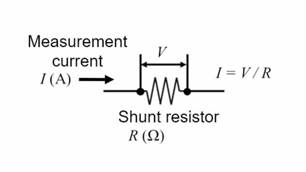
Figure 1. Principle of current detection by shunt resistor

2. Calorific value of shunt resistors

As explained, a shunt resistor generates heat based on its mechanism.
Then, how much heat does a shunt resistor actually generate?
See Figure 2. The surface temperature of a shunt resistor was measured under the conditions shown at the righthand side. We found that the temperature rose to about 80℃ at the highest point. Its temperature increment is 55℃. 

Since the temperature increment is proportional to the calorific value, it will be doubled if the resistance value is doubled, and will be quadrupled if the current value is doubled. Therefore, a shunt resistor is not suitable for measuring large currents. Generally, the magnitude of the current that can be used without any concern about heat generation is said to be around 10Arms.

Temperature rise can be controlled by reducing the resistance value of the shunt value provided that the same amperage is supplied. However, if the resistance value decreases, the voltage (V=IR) across the shunt resistor also decreases. The sensing voltage of the shunt register needs to be at a level that satisfies a sufficient S/N ratio in the subsequent signal processing. Therefore, it is not desirable to reduce the resistance value only for reducing heat generation.

Experimental conditions

・Shunt resistance = 5mΩ  ・Size = 6432 (6.4 x 3.2mm)
・Amount of current = 20A
・Room temperature (25°C) under natural air cooling

Thermal image of shunt resistor 
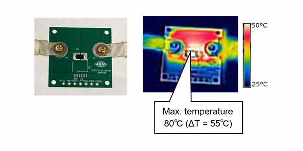
Figure 2. Thermal image of shunt resistor

3. Impact of heat generation

As explained, it is difficult to reduce heat generation by lowering the resistance value due to the trade-off between the heat generation of the shunt resistor and the S/N ratio. So what can go wrong if the shunt resistor generates heat? There are two main problems.

1. Cost increase and parts size increase

Electronic components such as shunt resistors may be damaged due to excessive heat generation. For this reason, electronic components are rated and must be used safely with a margin. Generally, the larger the rating, the higher the cost and the larger the size.

Printed Circuit Boards(PCB) used in industrial equipment such as a motor or inverter contain a variety of components. In recent years, due to the integration at factories and other factors, these printed circuit boards have become smaller in size. In other words, many components are packed within a small printed circuit board. Therefore, the ambient temperature of other electronic components rises due to the heat generated by the shunt resistor. As a result, it is necessary to select other components with large ratings such as the operating environment temperature, thereby increasing the entire system cost and hindering integration/miniaturization.


2. Increasing complexity of circuits and the number of parts

The resistance value of the shunt resistor fluctuates depending on the temperature as well as the normal resistance. Since the detected voltage is proportional to the resistance value of the shunt resistor, if the resistance value changes due to the temperature rise caused by heat generation, a deviation occurs in the calculated current value. Therefore, in order to accurately detect the current with the shunt resistor, a temperature correction circuit is required to compensate for the temperature change of the shunt resistor. This makes the circuit more complex and hinders miniaturization by increasing the number of parts.

In this way, heat generation of the shunt resistor has a significant impact on the entire system.

Circuit diagram when using a shunt resistor 
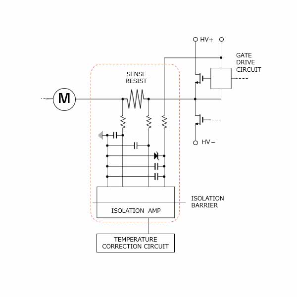
Figure 3. Circuit diagram when using a shunt resistor

4. To control heat generation of a shunt resistor

You have found the impact of the heat generated by a shunt resistor on the system and understand the importance of controlling the heat generation. Then, how can heat generation of a shunt resistor be controlled? To control the impact of shunt resistor heat generation on the system, heat can only be dissipated to the outside of the system because the calorific value itself cannot be reduced.

heat dissipation occurs due to the transfer of heat to other substances and the air as a result of three phenomena: heat conduction, convection (heat conduction to the air), and radiation. Since the amount of heat dissipationd by radiation is not large at 100°C or lower, devising a method for radiation does not have much effect on the heat generation of the shunt resistor. Therefore, we will introduce how to enhance the heat dissipation effect of the equipment by utilizing heat conduction and convection.

1.Improvement of heat generation by heat conduction

There are three ways to improve heat generation by heat conduction.

1-1. Innovations using printed circuit board wiring

1-2. Innovations using printed circuit board vias

1-3. Innovations based on the type of shunt resistors

1-1. Innovations using printed circuit board wiring

Heat escaping from the component to the printed circuit board is transferred inside the printed circuit board by "heat conduction". Since a copper foil, which is a printed circuit board wiring, has a high thermal conductivity, the larger the area of copper foil, the greater the amount of heat that escaped in the horizontal direction, and the larger the thickness or the number of layers, the greater the amount of heat that escaped in the vertical direction, respectively. As a result, the temperature rise of a shunt resistor can be suppressed (see Figure 3). However, this method poses problems such as increased cost per unit area of the printed circuit board and increased printed circuit board size.

The data below are all calculated using the following shunt resistor.

・Resistance value = 5mΩ  ・Size = 5025  (5.0 x 2.5mm)

Unless otherwise specified, the environment and printed-circuit board are as follows

・Environmental temperature = 25°C
・Board size = 30cm square  ・Copper foil thickness = 70um
・Wiring area = 20mm x 40mm  ・Number of wiring layers = 4

Figure 4. Ingenuity with board wiring Figure 4. Ingenuity with board wiring

1-2. Innovations using printed circuit board vias

Changing the number of vias and the thickness (diameter) of the vias also changes heat conduction. Figure 4 shows the result of the rising temperatures by changing the number of vias and the diameter. The result of the calculation shows that the number of vias is large and the larger the diameter, the greater the amount of heat escaping. Heat can also be dissipated more efficiently by placing vias close to or directly below the shunt resistor. However, there are limits to the effects of the number and diameter of the vias. The price of the printed circuit board may also increase as the number of vias increases.


1-3. Innovations based on the type of shunt resistors

Some shunt resistors have high heat dissipation performance. Such a product improves the heat dissipation performance to the printed circuit board and prevents the temperature from rising. They are more expensive than common shunt resistors. In addition, since the resistance value is not lowered, there is a limit to controlling the temperature rise.

Conditions

・Amount of current  = 20A  ・Distance between component and via = 2mm
・Via plating thickness = 20μm

Figure 5. Ingenuity with board vias Figure 5. Ingenuity with board vias

2.Improvement of heat generation by convection

There are two ways to improve heat generation by convection.

2-1. Utilizing forced air cooling

2-2. Devising heat dissipation components

2-1. Utilizing forced air cooling

Cooling air forcibly by increasing the wind speed using a fan and so on is called forced air cooling.heat dissipation by convection is proportional to half the power of the wind speed.Therefore, the higher the wind speed, the greater the heat dissipation. (Refer to Figure 6.)
However, the housing must have a vent in order for the fan to dissipate the heat.
If a vent is provided, it will be susceptible to water and dust and the operating environment will be restricted. In addition, the cost of installing a fan is naturally increased.

The data below are all calculated using the following shunt resistor.

・Resistance value = 5mΩ  ・Size = 5025  (5.0 x 2.5mm)

Unless otherwise specified, the environment and printed-circuit board are as follows

・Environmental temperature = 25°C
・Board size = 30cm square  ・Copper foil thickness = 70um
・Wiring area = 20mm x 40mm  ・Number of wiring layers = 4

Figure 6. Ingenuity using forced air cooling Figure 6. Ingenuity using forced air cooling

2-2. Devising heat dissipation components

heat dissipation performance can be improved by attaching a heat dissipation component called a heat sink directly below the heat generating part or on the printed circuit board as shown in Figure 6.heat dissipation by convection is increased by increasing the surface area by using materials with high thermal conductivity. With this method, new parts are installed for heat dissipation only, which poses issues on cost and size.


In this way, there are various heat dissipation measures.Although there are cost and size issues, it is possible to lower the temperature of the system.

You can simulate how much heat can be dissipated by what kind of measures. This is called thermal design, which reduces the probability of design failure by conducting simulation in advance to avoid possible problems of this nature. Since a shunt resistor generates a large amount of heat, this thermal design approach is indispensable.

Figure 7. Heat dissipation components Figure 7. Heat dissipation components

5.Difficulty of heat dissipation due to a closed system

I would like to consider a little more about the type of shunt resistors introduced in 1-3 in the previous chapter and the forced air cooling introduced in 2-1.

In recent years, automation has been advancing in factories and other facilities and the use of robots has increased.For example, when using a robot in a food factory, the robot must be cleaned for hygiene reasons and sealed for waterproofing (compliant with IP standards).However, heat cannot escape to the outside if it is sealed.How much will the temperature rise change when it is sealed in housing and when it is naturally air-cooled in the atmosphere?
Let's look at the high heat dissipation type of resistor, which has a lower temperature rise than the normal shunt resistor under natural air cooling.

We compared the results of the open system and the closed system. (Refer to Figure 8.)
As shown in the diagram, even if the temperature rise remains low in the open air system, once the area is sealed, the temperature rises greatly because the heat escape area disappears. This tendency is more pronounced as the amperage increases. Even if heat dissipation performance is improved, the temperature rises as sealing and integration progresses since the heat cannot be dissipated as expected.
After all, control of the calorific value itself is an important factor in terms of safety and cost.

Experimental conditions

・Shunt resistance = 5mΩ  4W rating  ・Size = 5025 (5.0 x 2.5mm)

*In this experiment, a shunt resistor with higher heat dissipation than usual (refer to 1-3. in the previous section) was used.

・Amount of current = 10, 14, 20A

The temperature of this shunt resistor is measured in two environments, one is in open and the other is in sealed condition.

Figure 8. Comparison of temperature rise between sealed and open condition of shunt resistor Figure 8. Comparison of temperature rise between sealed and open condition of shunt resistor

Current sensor of low heat generation, "Currentier"

So far, we have been explaining a shunt resistor used for current detection for its current detection principle, cause of heat generation, calorific value, impact of heat generation, and method of heat dissipation.

As explained, while shunt resistors are simple in principle and easy to use, they generate large amounts of heat and require heat dissipation measures, making them unsuitable for large current measurements and sealed environments. According to the feedback from the customers talk, 10 to 20Arms seems to be the current limit of shunt resistors. What can be done to detect the current easily without worrying about heat generation in any application? 

One of the current sensing methods is a coreless current sensor IC using a Hall element. Since coreless current sensor ICs use the output of a Hall element, the resistance of the primary conductor is reduced as the resistance value is not directly related to the S/N ratio. AKM's "Currentier" generates very little heat among coreless current sensors ICs.

Figure 9 shows a thermal image of the comparison of calorific values of a shunt register (normal type in Section 2) and Currentier after the current of 20A is supplied for 10 minutes by using the identical printed circuit boards. This shows that the shunt resistor generates heat up to ΔT=55°C, whereas Currentier generates heat as little as ΔT=3°C.

Figure 9. Comparison of temperature rise between shunt resistor (top) and Currentier (bottom) Figure 9. Comparison of temperature rise between shunt resistor (top) and Currentier (bottom)

Temperature increment quantities of Currentier were also measured at 10A, 14A, and 20A for both the closed air system and the open air system. The results were also compared with those of shunt resistors (high heat dissipation types in Section 5). Figure 10 shows the results. A shunt resistor of high heat dissipation type has a very high temperature rise when sealed, but, in Currentier the temperature is kept low even if it is sealed. The reason for this is that the resistor of Currentier is very small at "0.27mΩ".

In the future, low heat generation will be more important than heat dissipation performance at detection of current in a sealed environment.

Figure 10. Comparison of temperature rise between shunt resistor and Currentier sealed and open conditions Figure 10. Comparison of temperature rise between shunt resistor and Currentier sealed and open conditions

We have prepared a heat generation simulation tool for customers who want to check the heat generation in a way similar to an actual system. By entering the board and environmental conditions, you can calculate the temperature rise relative to the effective current immediately.
This tool can also simulate different resistance values and compare them with shunt resistor, cement resistor, etc. We hope you will find it useful in your thermal design.

Currentier offers a variety of other benefits in addition to low heat generation, thus helping customers solve their problems. For details, see the following link.