-
Products

-
Applications
-
Support
-
About AKM
Next-generation power devices (SiC/GaN)
Current Sensors
This page outlines AKM's recommended products, along with their advantages, which are most suitable for current detection in the following two commonly used next-generation power device applications using SiC and GaN.
1. Totem pole PFC circuit
2. Phase-shift DCDC circuit
Next-generation power devices
Issues of Si Power Devices
Power devices are semiconductor devices used in power systems. Currently, Si-IGBTs and Si-MOSFETs are widely used in power devices. By setting the switching operation of power devices at a higher frequency, passive components such as coils and transformers can be made smaller, thereby achieving "system miniaturization". However, with Si-MOSFETs and Si-IGBTs, higher frequency operation results in higher losses during the switching operation, making it impossible to achieve "higher system efficiency". Therefore, in power systems using Si-IGBTs and Si-MOSFETs, it has been difficult to achieve both "system miniaturization" and "system efficiency".
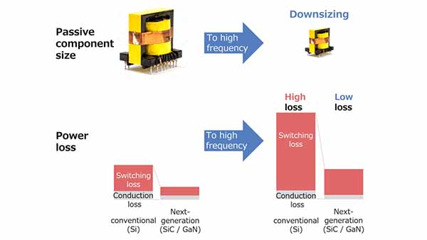 Figure 1. Changes in size and switching loss due to higher frequency of power device (Si to SiC and GaN)
Advantages of next-generation power devices
On the other hand, SiC-MOSFETs and GaN-MOSFETs, the next generation power devices, have very low loss during high-frequency switching operation, enabling the downsizing of passive components without compromising the conversion efficiency of the system. For this reason, SiC-MOSFETs and GaN-MOSFETs are attracting attention as next-generation power devices, and are beginning to be used in a wide range of applications, including power supplies for EVs and servers, industrial equipment, UPS (uninterruptible power supplies), and Photovoltaic Power conditioner. Figure 2 compares the power capacities and switching frequencies of power devices that use Si, SiC, and GaN, and shows typical applications that have power systems that use these devices.
The transition from Si to SiC and GaN power devices will allow for higher power capacity and higher switching frequency ranges.
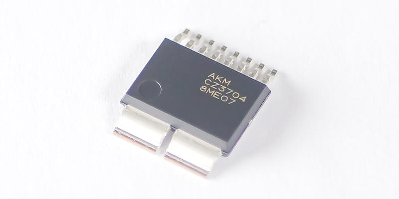
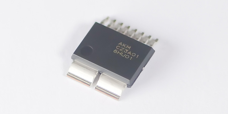
AKM's current sensors are suitable for current detection in SiC and GaN applications because of their compact size, 60Arms capability, and fast response time.
In the future, AKM will further promote the increase of the current and bandwidth to meet the expanding applications of SiC and GaN. In the following section, we explain the features and how to select the most suitable current detection method for "Totem pole PFC circuit" and "Phase-shift DC-DC converter circuit", which are the mainstream in typical applications.
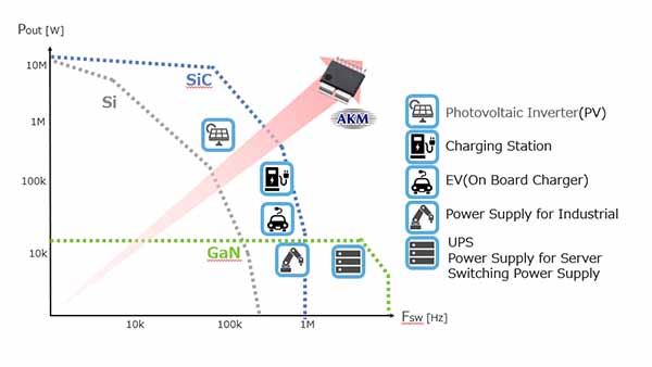 Figure 2. Comparison of power capacity and switching frequency in major applications of next-generation power devices
Totem pole PFC circuit
*PFC is an abbreviation for Power Factor Correction.
With the enactment of harmonic current suppression regulations, PFC has been incorporated in switching power supplies. The conventional mainstream PFC circuits that use diode bridges have a large power loss in the diode bridge section, hindering the "increase of system efficiency". "Totem pole PFC circuits" that use power devices with low power loss instead of diode bridges are attracting attention as the solution to this problem. By using next-generation power devices with low power loss, it is possible to achieve both "high system efficiency" and "system downsizing" even at high frequencies. In the following section, we will introduce the characteristics required for the current detection section to take full advantage of the totem pole PFC circuit.
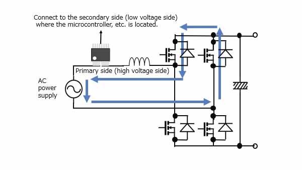 Figure 3. Totem pole PFC circuit
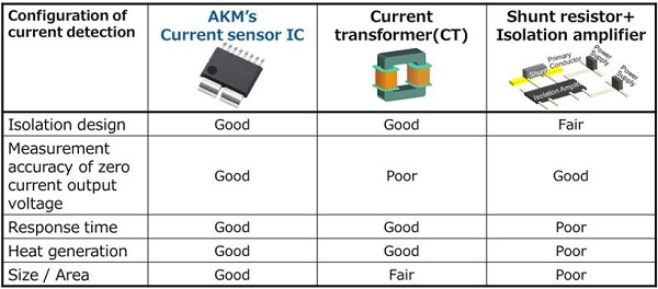
The following five items are important for the current detection section of the totem pole PFC circuit.
- High isolation design
- Measurement accuracy of zero current output voltage
- Response Time
- Heat generation
- Size/Area
Table 1 compares AKM's current sensor ICs, current transformers (CTs), and shunt + isolation amplifiers in terms of the above five criteria. AKM's current sensor IC is the only current detection method that can meet these five important criteria. On the other hand, the CT and shunt + isolation amplifier configurations have their own issues. In the following section, we will explain why each item is important and the advantages and disadvantages of the three current detection methods.
Table 1. Comparison of current sensing methods
1. High isolation designs
The conventional PFC circuit detects the current that flows to ground (hereinafter referred to as GND). However, in the totem pole PFC circuit, since some current path does not flow through to GND (the path through the blue line in Fig. 3) depending on the ON/OFF combination of switching elements, it is necessary to detect the current on the high side of the AC power supply. Therefore, the current detection section needs to be isolated between the primary and secondary sides.
The shunt resistor + isolation amplifier requires power supplies to drive the isolation amplifier on the primary and secondary sides, thereby complicating the circuit configuration.
AKM's current sensor ICs and current transformers do not require a power supply on the primary side, making isolation design less complicated.
2. Measurement accuracy of zero current output voltage
In a totem pole PFC circuit, it is necessary to accurately detect the timing of input current polarity switching.
Therefore, measurement accuracy of zero current output voltage is required for the current detection section. Since CTs are affected by magnetic hysteresis, this zero-current measurement accuracy is an issue.
AKM's current sensor IC has the advantage of high measurement accuracy of zero current output voltage because it has no magnetic hysteresis.
3. Response Time
Since the short-circuit tolerance of next-generation power devices is short, it is necessary to detect and protect against overcurrent instantaneously. Therefore, the current detection section needs to have a fast response time. In order to achieve fast response time with CT, the CT size needs to be increased, which becomes an issue. Generally, the response times of CT and Shunt + isolation amplifiers are 1μsec or more so that they are not suitable for protecting next-generation power devices with short-circuit tolerance. AKM's current sensor ICs are compact and have a response time of less than 1μsec, making them ideal for overcurrent detection in next-generation power devices.
4. Heat generation
When the current detection section generates a large amount of heat, a large heat dissipation area needs to be secured as a countermeasure against heat generation. This becomes a problem in terms of "system downsizing". In the configuration of a shunt resistor + isolated amplifier, a large amount of heat is generated by the current flowing through the shunt resistor. AKM's current sensor IC has a small resistance value of 0.27mΩ in the primary conductor through which the current flows. This reduces heat generation (heat generation is about 1/10 compared to a 3mΩ shunt resistor), thereby contributing to system downsizing.
5. Size/Area
Large component sizes and areas hinder "system downsizing".
In order to achieve fast response time with CTs, the size of the CTs needs to be large, which becomes a problem. Shunt + isolation amplifiers require various peripheral components, such as primary and secondary power supplies and input filters, thereby increasing the mounting area. AKM's current sensor IC has a small package size and does not require such peripheral components as those mentioned in the shunt + isolation amplifier configuration, making it ideal for "system downsizing".
For more information please click on link below.
Our recommendation
Please refer to the "Selection Table".
Phase-shift DC-DC converter circuit
The phase-shift DC-DC converter circuit is one of the most conversion-efficient DCDC circuits (see Figure 4). By using next-generation power devices with low power loss, the phase-shift DCDC circuit can in principle reduce the size of passive components (mainly transformers) by increasing the frequency, similar to the totem pole PFC circuit. In order to avoid magnetic saturation, which is a problem in downsizing transformers, "peak current control" is available. This method is to control the current flow until just before the magnetic saturation point. In this method, it is important to measure the peak current accurately without delay. CTs are mainly used for this current detection method, but there are two issues that need to be addressed in order to further reduce the size of transformers by increasing the frequency.
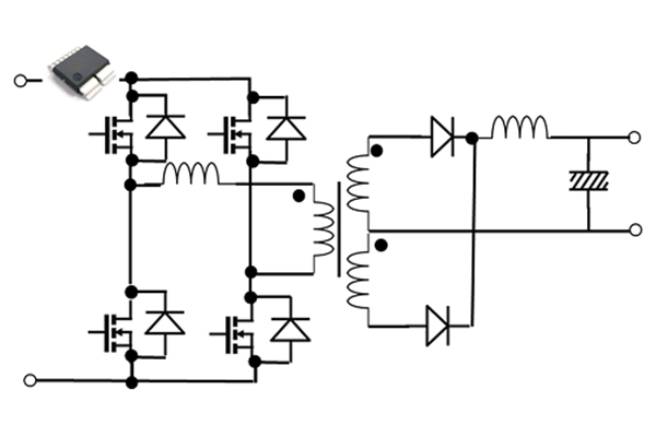 Figure 4. phase-shift DC-DC converter circuit
The first issue is the bandwidth of the CT. A wide bandwidth is required to detect the peak current without delay, but the size of the CT must be large in order to achieve a wide bandwidth.
The second issue is the measurement accuracy of the CT. Measurement accuracy refers to the combined accuracy of zero-current-voltage, nonlinearity, and current sensitivity. CTs are affected by magnetic hysteresis and other factors, resulting in poor measurement accuracy and inability to accurately detect peak currents. As transformers become smaller, the magnetic saturation point becomes lower, requiring higher peak current measurement accuracy, which is difficult to achieve with CT.
In comparison, AKM's current sensor ICs have the following features.
- Wide bandwidth
- High accuracy
AKM's current sensor IC, which has a wide bandwidth and a small package, does not have such a size issue as that of CTs even at high frequencies. Also, due to its high accuracy, the current sensor IC can accurately detect peak currents and can be miniaturized, avoiding magnetic saturation of the transformer even at high frequencies.
For more information about AKM's current sensor IC (Currentier), please refer to the following.
Our recommendation
Please refer to the "Selection Table".
Selection Table
| Current Sensor Type | Package | Supply Voltage | Output Voltage | Maximum Primary Current | Measurement Range | Bipolar / Unipolar | Ratiometric/ Non-Ratiometric | Creepage Clearance | Working Voltage * | Product Name | Product Series | Part Status |
|---|---|---|---|---|---|---|---|---|---|---|---|---|
| (V) | (V) | (Arms) | (Apeak) | (mm) | (Vrms) | |||||||
| Coreless | SOP | 5.0 | 5.0 | 100 | ± 115 to ± 225 | Bipolar | Retiometric | ≧ 8.0 | 1118 | CZ375x | CZ375 Series | MP |
| 60 | ± 5.3 to ± 180 | CZ370x | CZ370 Series CZ372 Series | MP | ||||||||
| 0 to 345.2 | Unipolar | CZ372x | ||||||||||
| 3.0 | 50 | ± 11.6 to ± 166.6 | Bipolar | Non-Ratiometric | CZ3AGx | CZ3A Series | MP | |||||
| 3.3 | 3.3 | ± 12.9 to ± 129.1 | CZ3A0x |