-
Products

-
Applications
-
Support
-
About AKM
Motor Error Calculation Tool
Current Sensor
In a servo motor, the amount of torque is determined by feedback control of the amount of current flowing through the motor, so the error in the current sensing circuit block is directly related to the error in the amount of torque.
Since this torque amount error also affects the machining accuracy of the machine tool, the error in the current sensing circuit block is a very important parameter in the design of a servo motor.
"Motor Error Calculation Tool" allows you to easily calculate the relationship between a torque error and the current sensor of a servo motor. By entering the information of the servo motor that is used and the information relating the current detection and selecting AKM's current sensor to be compared, you can estimate how the torque accuracy will improve by replacing the existing current detector.
*Caution * This tool is intended to simply compare the effects of the current detector. Therefore, the motor information and feedback loops are simplified and ideal conditions are applied. Please note that the degree of error is different from that of the actual device.
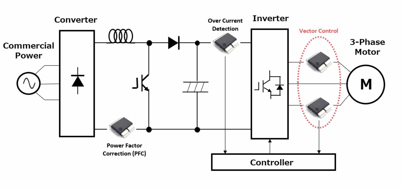 Figure 1. Block diagram of the inverter circuit
How to use
This tool allows you to compare and compute in 2 steps.
*This tool calculates the magnet torque where d-axis current (id) = 0.
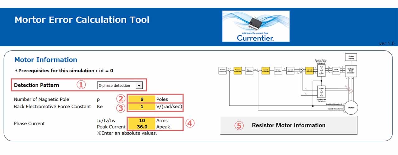 Figure 2. Motor information input screen
[Step1] Enter motor information.
(1) Select a current detection method, 2-phase or 3-phase.
(2) Enter a number of magnet poles used.
(3) Enter a back EMF constant.
(4) Enter the items related to the phase current (the effective current and the maximum current to be detected).
(5) Press the Register Motor Infomation button.
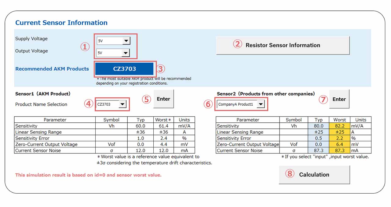 Figure 3. Current sensor information input screen
[Step2] Enter the current sensor information
(1) Select Supply Voltage (5V/3.3V) that is supplied to the current sensor and the Output Voltage (5V/3.3V) and (2) press the Register Sensor Information button.
(3) The recommended current sensor is displayed based on Supply Voltage, Output Voltage, and the maximum current entered in Item (4) of [Step1].
(4) Select Sensor 1 (AKM-product brand) and press ENTER.
(5) The characteristics of the selected AKM product are displayed.
* If you wish to test this tool first before studying the product, select the current sensor that was recommended in item (3).
* Further details of our products are available by searching from Lineup.
* The Typ values that are displayed indicate the guaranteed ranges at room temperature.
* The Worst values indicate the reference values equivalent to ±3σ considering the thermal properties.
(6) Sensor 2 information registry (current sensor to be compared). If you choose other companies' products, please select from "Company A Product 1,2" and "Company B Product 1,2", and then click (7) "Enter" button. If you want to input the information of your current sensor, select "Input" and click (7) "Enter" button.
* If you select "Company A Product 1,2" or "Company B Product 1,2", the characteristics of other companies' products will be displayed in the table.
* If you select "Input", the table will be blank, so please input the information of your current sensor in the yellow column.
*Press the ENTER button to reset the input contents.
*Examples of products from other companies are current sensors with cores and coreless current sensors of general specification values.
(8) Press the Calculate button.
Confirmation of simulation results
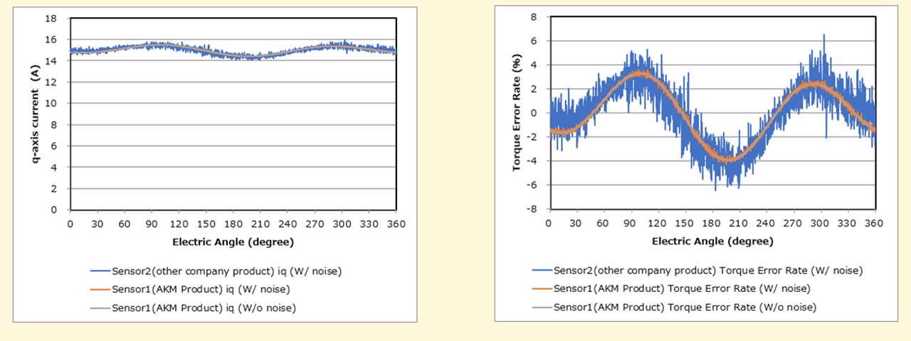 Figure 4. Simulation calculation results
*This tool assumes the worst case considering the temperature characteristics of the current sensor.
Left diagram Horizontal axis: Electric angle, Vertical axis: q-axis current
1. Sensor 2 (current sensor of other company) iq (current sensor noise = Detected)
2. Sensor 1 (AKM Current Sensor) iq (Current Sensor Noise = Detected)
3. Sensor 1 (AKM Current Sensor) iq (Current Sensor Noise = Not detected)
Right diagram Horizontal axis: Electric angle, vertical axis: Torque error rate
1. Sensor2 (Current Sensor of other company) T Error Rate (Current sensor Noise = Detected)
2. Sensor1 (AKM Current Sensor) T Error Rate (Current Sensor Noise = Detected)
3. Sensor 1 (AKM Current Sensor) T Error Rate (Current Sensor Noise = Not detected)
1. refers to the result produced by including the sensitivity error, zero current output voltage error, and noise of other companies' current sensors.
2. refers to the result produced by including the effect of noise in 3.
3. refers to the calculation result when only the sensitivity error and zero current output voltage error of the current sensor of AKM are included.
These results show that the effect of noise is small in AKM's sensor due to its low noise. On the other hand, current sensors of other companies have large noise, resulting in large errors.
This tool should be used on your PC.
* Please read our Terms and Conditions ,and Privacy Policy before using this service.
What is the relationship between the torque error and the current sensor ?
The motor drive system comprises a control loop; starting from the innermost, a current control system that controls the current, a speed control system that controls the speed, and a position control system that controls the position. For an application that requires speed control only such as vehicles, the motor drive system comprises speed control system and for an application that requires movements to a target position such as a robot, a configuration involving up to the position control system is required.
Since the current control system is located on the innermost position of the motor control system, it also has a significant impact on the outer control systems. Therefore, high speed and high accuracy design is essential for the current control system.
The current control system controls the torque corresponding to the acceleration. Since the torque is proportional to the amount of current flowing through the motor, adjust the amount of current in proportion to the load applied to the motor.
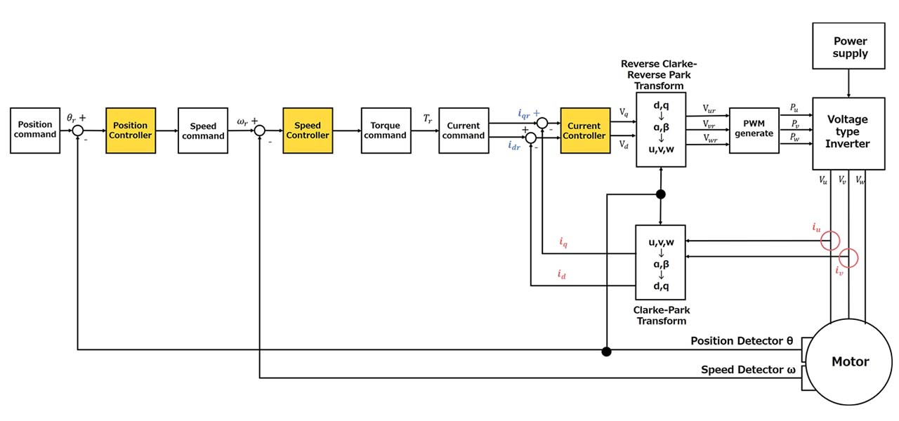 Figure 5. Motor Drive System Configuration
id and iq are the d-axis current and q-axis current used in vector control, respectively. The currents iu, iv, and iw flowing in each phase can be expressed as follows.
iu = Iusinθα
iv = Iusin(θα - 2π/3)
iw = Iwsinθα + 2π/3)
The following equation describes how the sensitivity error of the current sensor and zero current output voltage error affect the accuracy of the torque (T).
T = iu(K+1) + iv + iw + ioff + inoise
Iu, iv, iw : Current flowing in each phase, K : Sensitivity error of the current sensor, ioff: zero current voltage error of the current sensor, inoise : Noise of the current sensor
*This tool calculates the magnet torque when d-axis current (id) = 0.
The above equation indicates that the sensitivity error, zero current voltage error, and noise of the current sensor all affect the torque error of the motor.