-
Products

-
Applications
-
Support
-
About AKM
Reducing Design Man-hours
In this page #2, we would like to explain how Currentier can contribute to "Reducing Design Man-hours".
Current Sensors
Many control devices, such as general-purpose inverters for controlling motors, AC servo motor drives for precise position control, and controllers for robots to automate operations, need to support motors with various load capacities and torques depending on applications. With regard to current sensing in three phase motors combined with these various control devices, there is a strong need to reduce extra design man-hours as much as possible so that more man-hours can be spent on improving the performance of the devices themselves.
Currentier can contribute to reducing design man-hours by following five reasons:
- Low Heat generation
- Supporting a wide current measurement range
- No need for isolated power supply on the primary side
- Excellent temperature characteristics
- No need to set up a new test environment
1. Low heat generation
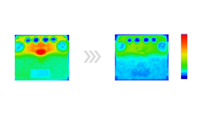
Compared to other solutions, Currentier has a lower resistance of the primary conductor, which reduces heat generation and heat dissipation area. It can significantly reduce the size of the board and chassis. The low heat generation of Currentier itself can also significantly reduce man-hours required for thermal design (*1). As you can see in Figure 1 and 2, it is obvious that there is a big difference in the heat generation. When 40A is applied for 10 minuets, Currentier generates about 50℃ less heat than a shunt method, and about 20℃ less heat than a general coreless current sensor IC.
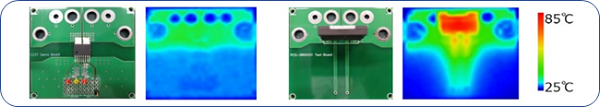 Figure 1. Comparison between Currentier and a shunt resistor in heat generation
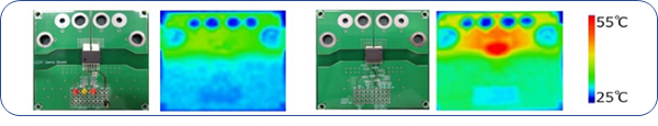 Figure 2. Comparison between Currentier and a typical coreless current sensor IC in heat generation
(*1 : For more details, click #01 System Downsizing)
2. Supporting a wide current measurement range
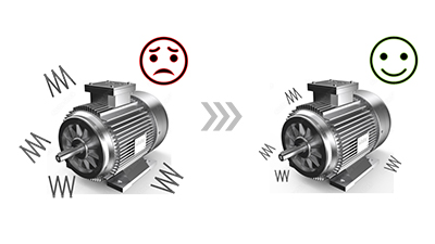
For servo motor drives and general inverters which have many products lineup, it has been necessary to use shunt resistors in parallel or a cored current sensor depending on the capacity of the current.
In the case of using shunt resistors, it is necessary to change the resistance values depending on the capacity and the amount of the current. When the measurement current is small, the resistance value needs to be increased to increase the S/N. In contrast, when the measurement current is large, the resistance value needs to be lowered or the heat generation is too high. Changing the resistance value for each model requires design and verification for each model, and thus it takes a lot of man-hours.
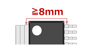
However, as for Currentier, it has creepage/clearance distance of 8mm or more and can be used both for 400V and 200V in the same package. Currentier supports wide current measurement range of ±5Apeak to ±180Apeak and is available for seven different sensitivities (Table 1). Therefore, Currentier can use the same circuit layout without depending on the capacity and can contribute to reducing design man-hours (Figure 3).
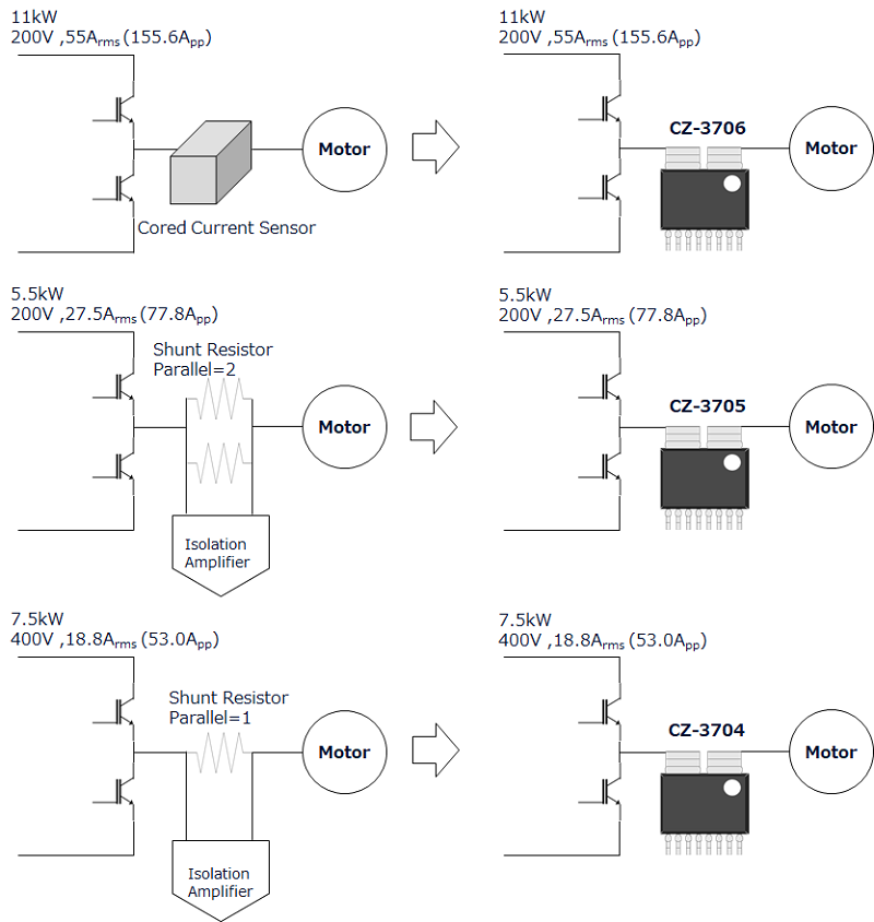 Figure 3. Use case of different inverter capacities
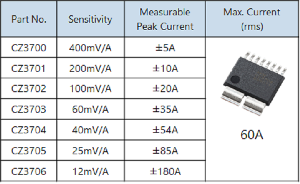
Table 1. Product lineup of CZ-37 series
3. No need for isolated power supply on the primary side
In the case of the shunt + isolation amplifier, it is necessary to prepare power supplies for both primary and secondary sides, and an insolated power supply is required for primary side. It is because there are elements on each side and it is required to be driven in isolated condition (Figure 4).
In the case of the isolation amplifier (photo-coupler), the primary side drives LEDs and the secondary side receives the lights. Isolation is achieved by exchanging signals of light.
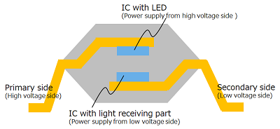 Figure 4. Example of internal structure of isolation amplifier
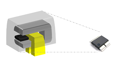
In contrast, as for coreless current sensor ICs, there is no elements on the primary side, but only the primary conductor is on the primary side (Figure 5). Therefore, no power supply for the primary side is needed, and thus it can be driven only by an uninsulated power supply on the secondary side. The reason why elements are not required on the primary side is that the signal between the primary and secondary side is transferred by a magnetic field. The primary conductor is a current path made of Cu, which acts like an element that creates a magnetic field.
The isolated power supply to run the isolation amplifier is from diodes, resistors or capacitors on the isolated side. In order to ensure isolation, wiring on high voltage side must be kept at a certain distance from the low voltage side, which restricts the layout and makes wiring complicated. As a result, substrate area are increased and more design man-hours are needed.
However, as for a coreless current IC, there is only a current path on the primary side, which makes layout simple. As a result, it can contributes to reducing substrate area and design man-hours.
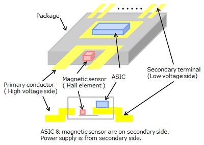 Figure 5. Internal structure of coreless current sensor IC
4. Excellent temperature characteristics
Currentier is equipped with EEPROM and compensates its temperature characteristics before shipment, so that it can achieves high current detection accuracy all the times.
The ambient temperature around the current sensor increases during system operating, thus temperature characteristics above 0℃ are important. The characteristics of CZ375, CZ372, CZ370 series are compensated before shipment in order to reduce the error in the temperature range above 0℃, and thus it can be provided in the best for the customer's usage.
If the current detection accuracy is insufficient, extra test before shipment with peripheral parts is required. However, Currentier originally has such an excellent temperature characteristics that there is no need to compensate by shipping test with current flow. As a result, Currentier contributes to reducing design man-hours of creating extra correction programs for tests before shipment.
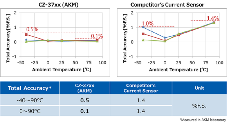 Figure 6. Temperature characteristics comparison of Currentier and other coreless current sensor IC
5. No need to set up a new test environment
There is another method of current sensing that draws a wiring pattern of the current to be measured on a board and places a current sensor on it (Figure 7). However, this method makes inaccurate and difficult to use because of the influence of mounting misalignment to the substrate and manufacturing variations.
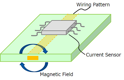 Figure 7. Current sensor IC with PCB wiring pattern
In order to achieve high accuracy with this method, it is necessary to correct the output of the current by test with the mounted board, which increases design man-hours and makes production TAT longer. Furthermore, in general, there is no test environment in which the current is applied to compensate, so that it needs man-hours to set up the new test environment.
In contrast, Currentier draws current into the package and measures a magnetic field, so that there is no influence of a mounting misalignment or a board manufacturing variation. Therefore, the conventional test environment can be used as it is, and thus it can reduce design man-hours.
Summary
AKM's coreless current sensor IC Currentier contributes to "Reducing design man-hours" by
・Reducing thermal design process by low heat generation
・Sharing the same system configuration regardless of capacity
・No need for isolated power supply on the primary side
・Reducing test programming process due to an excellent temperature characteristics
・No need to adjust sensitivity after mounting on the board
Recommend
Solutions
If you would like to know more about how Currentier can solve problems, please click below links.
Applications
If you would like to consider proper products from application examples, please click below links.
Products
For more detailed information about each product series, and for selection of specific products, please click below links.