
CZ37 Series
-
[Q0338]
・Is it possible to sense both DC current and AC current?
-
A.
・It is possible to sense both DC current and AC current.
Was it helpful?YesNoThank you We will reflect your opinion on the improvement of the web content.
-
[Q0339]
・What is the difference between maximum primary current and linear sensing range?
-
A.
・Maximum primary current indicates the current value which can be applied for a long time in a current sensor and depends on the cross-sectional area of the primary conductor.
CZ-370x, CZ-372x can be damaged when they have been used for a long time over the maximum effective current value. If current flows at a short period within msec order, such as an over current, CZ-370x, CZ-372x is not damaged.
Was it helpful?YesNoThank you We will reflect your opinion on the improvement of the web content.
-
[Q0340]
・How much current can be flown in CZ-370x, CZ-372x?
-
A.
・It is possible to flow current of up to 60Arms in CZ-370x, CZ-372x.
Was it helpful?YesNoThank you We will reflect your opinion on the improvement of the web content.
-
[Q0341]
・Can CZ-370x, CZ-372x detect unipolar current? (ex. current detection of 0 to 21A)
-
A.
・CZ-370x, CZ-372x detects both bipolar and unipolar current.
Bipolar: CZ-370x series
Unipolar: CZ-372x series
Was it helpful?YesNoThank you We will reflect your opinion on the improvement of the web content.
-
[Q0342]
・How small current can the CZ-370x, CZ-372x resolve?
-
A.
・The current resolution is determined by its output noise voltage.
The current resolution can be increased by applying a noise filtering circuit.
(a) 0.1μF bypass capacitor should be placed close to VDD and VSS pins of CZ-370x, CZ-372x.
(b) Add a low-pass filter if it is necessary. The C1 values should be fixed in consideration of load conditions.
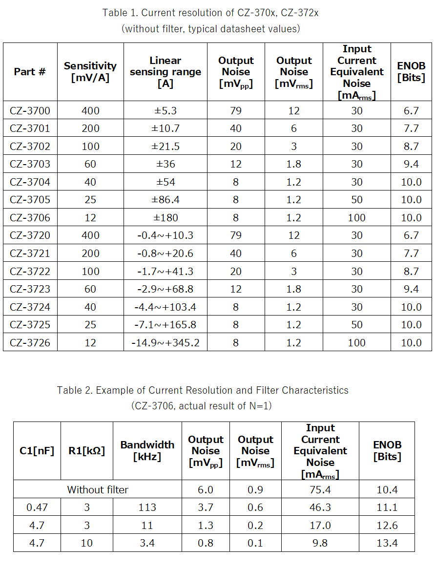
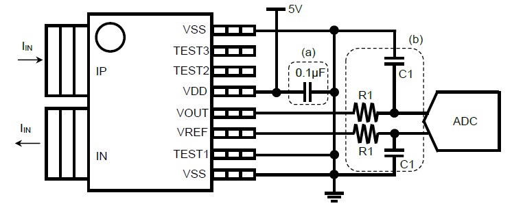
Figure 1. External Circuit example Was it helpful?YesNoThank you We will reflect your opinion on the improvement of the web content.
-
[Q0343]
・How much is the temperature drift of the primary conductor resistance of CZ-370x, CZ-372x?
-
A.
・The temperature drift of the primary conductor resistance of CZ-370x, CZ-372x is shown in Figure 2.
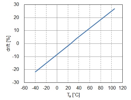
Figure2. CZ-370x, CZ-372x Temperature Drift of the Primary Conductor Resistance (normalized at 25°C) Was it helpful?YesNoThank you We will reflect your opinion on the improvement of the web content.
-
[Q0344]
・What is the variation in primary conductor resistance?
-
A.
・The primary conductor resistance of CZ-370x, CZ-372x varies from 0.21 to 0.30mΩ (reference) at 25°C.
Was it helpful?YesNoThank you We will reflect your opinion on the improvement of the web content.
-
[Q0345]
・What is the inductance of the primary conductor?
-
A.
・The Primary Conductor Inductance of CZ-370x, CZ-372x is about 3nH (reference) at 25°C.
Was it helpful?YesNoThank you We will reflect your opinion on the improvement of the web content.
-
[Q0346]
・What does "ratiometric" mean?
-
A.
・The CZ-370x, CZ-372x has a ratiometric output. This means that the output of the current sensor changes proportionally to the supply power voltage. A ratiometric output is suitable for applications where the output is converted to digital using an A/D converter and where fluctuation of the power supply voltage causes reference error of the A/D converter.
The supply voltage of the CZ-370x, CZ-372x and the reference voltage of A/D converter fluctuate at the same ratio. This will avoid the effects of the fluctuation of the power supply to the A/D converter output.
Table 3 shows the VDD dependence of VREF voltage.
Figure 3 shows the output voltage of the CZ-3702 (Sensitivity Vh=100mV/A) as an example ratiometric output.
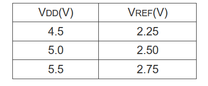
Table 3. VDD dependence of VREF voltage 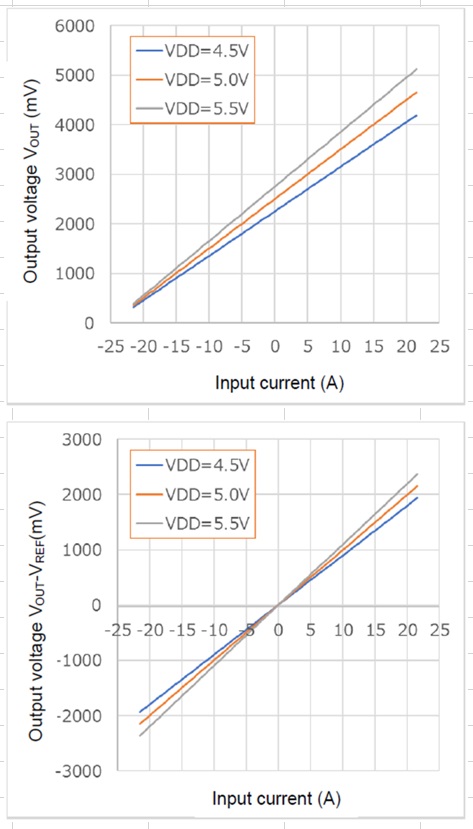
Figure3. Output voltage of the CZ-3702 vs Input current with different VDD. (Top: VOUT, Down: VOUT-VREF) Was it helpful?YesNoThank you We will reflect your opinion on the improvement of the web content.
-
[Q0347]
・How soon after power-on will a valid signal be available from the CZ-37xx?
-
A.
・Figure 4 shows a recommended example of the power up sequence.
In the power up sequence, if the time from VDD=3.7V to VDD=5V is less than 0.4msec, the output will be stabilized after 1.2msec (typ.) from the time VDD=3.7V. If it takes 0.4msec or more, it may take longer to stabilize the output. Please check the time needed to stabilize the output in that case.
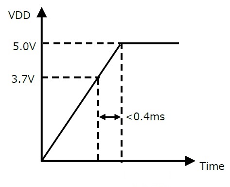
Figure4. Recommended example of the power up sequence Was it helpful?YesNoThank you We will reflect your opinion on the improvement of the web content.
-
[Q0348]
・What is the response time?
-
A.
・The response time of CZ-370x, CZ-372x is typically 1μs with a load capacitance of 1000pF.
Figure 5. shows the typical pulse response waveform. (Left: Rise response waveform, Right: Fall response waveform)
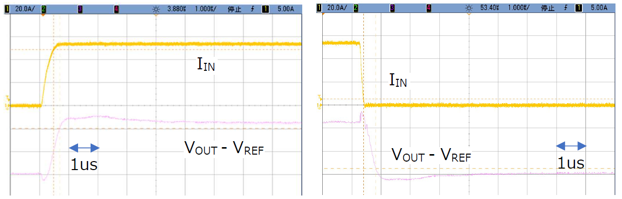
Figure 5. Pulse response waveform of CZ-370x, CZ-372x Was it helpful?YesNoThank you We will reflect your opinion on the improvement of the web content.
-
[Q0349]
・What is the recovery time from a fully saturated output?
-
A.
・The recovery time is 2μs or less.
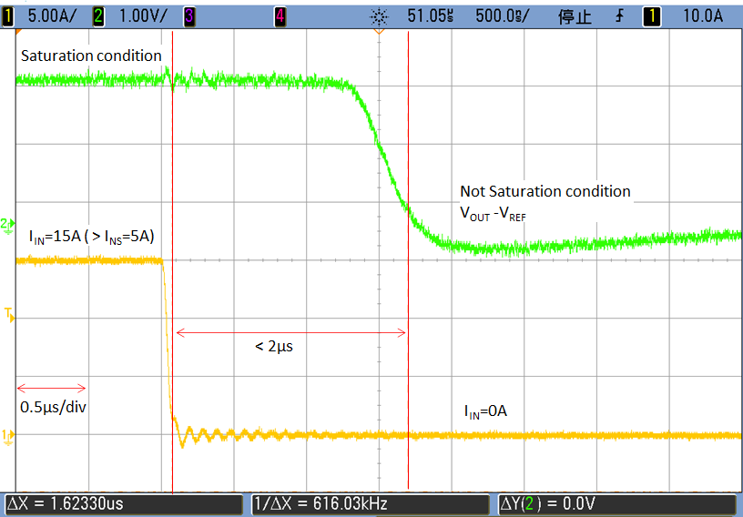
Figure 6. Response waveform of CZ-3700 (Saturation condition: IIN=15A → Not Saturation condition: IIN=0A) Was it helpful?YesNoThank you We will reflect your opinion on the improvement of the web content.
-
[Q0350]
・What happens if a load capacitance over 1000pF is inserted to the CZ-370x, CZ-372x VOUT?
-
A.
・CZ-370x, CZ-372x do not output the correct value because of the oscillation of output.
Was it helpful?YesNoThank you We will reflect your opinion on the improvement of the web content.
-
[Q0351]
・What happens if a load current over +/-2mA is applied to CZ-37xx VOUT?
-
A.
・In this case the CZ-37xx does not output the correct value.
Was it helpful?YesNoThank you We will reflect your opinion on the improvement of the web content.
-
[Q0352]
・Does CZ-370x, CZ-372x show magnetic hysteresis?
-
A.
・No, because CZ-370x, CZ-372x does not contain magnetic material.
Was it helpful?YesNoThank you We will reflect your opinion on the improvement of the web content.
-
[Q0353]
・What safety standards CZ-370x, CZ-372x have?
-
A.
・CZ-370x, CZ-372x is certified as IEC/UL 62368-1, UL 1577 by the international certification organization.

◾ IEC/UL 62368-1 Audio/video, information and communication technology equipment Part 1: Safety requirements Edition 2. (File No. E359197)
◾ CAN/CSA C22.2 No. 62368-1-14, 2nd Ed, Issued: 2014-12-01 (Audio/video, information and communication technology equipment Part 1: Safety requirements)(File No. E359197)
◾ UL1577 Non-Optical Isolators-Edition 5.(File No. E499004)
◾ CSA Component Acceptance Service No. 5A - Component Acceptance Service for Optocouplers and Related Devices (File No. E499004)
Was it helpful?YesNoThank you We will reflect your opinion on the improvement of the web content.
-
[Q0354]
・What is the clearance distance and the creepage distance?
-
A.
・The clearance distance and the creepage distance are both over 8.0mm.
Was it helpful?YesNoThank you We will reflect your opinion on the improvement of the web content.
-
[Q0355]
・What is the CTI of the package?
-
A.
・The Comparative Tracking Index (CTI) of the CZ-37xx package resin is 400V≦CTI<600. The Material Group is Ⅱ.
Was it helpful?YesNoThank you We will reflect your opinion on the improvement of the web content.
-
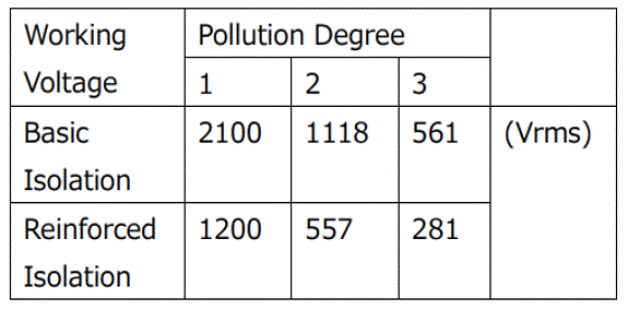
[Q0356]
・How much is the working voltage of CZ-370x, CZ-372x?
-
A.
・CZ-370x, CZ-372x can be used under the following conditions.
 Was it helpful?YesNoThank you We will reflect your opinion on the improvement of the web content.
-
[Q0357]
・Is it allowable to use this device over the rating isolation voltage of the data-sheet?
-
A.
・The device should be used within a recommended condition.
Was it helpful?YesNoThank you We will reflect your opinion on the improvement of the web content.
-
[Q0358]
・What is the voltage noise rejection ratio?
-
A.
・The Voltage Noise Rejection Ratio of the Primary Conductor was calculated by measuring the output while a high frequency sine wave voltage was applied as the input noise to the primary conductor.
Table 4 shows the CZ-370x, CZ-372x series having a strong voltage noise rejection ratio.
Figure 7. shows the frequency dependency of the voltage noise rejection ratio.
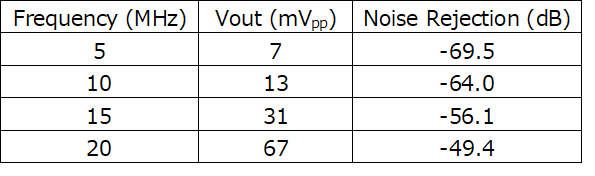
Table 4. Voltage Noise Rejection Ratio when high frequency sine wave voltage (20Vpp) is applied 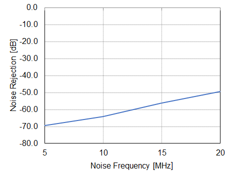
Figure 7. Noise Frequency vs Voltage Noise Rejection Ratio Was it helpful?YesNoThank you We will reflect your opinion on the improvement of the web content.
-
[Q0359]
・What are the constant parameters of RC?
-
A.
・Please decide the parameters considering the requirement of output resolution and response time (Please refer to [Q0342]).
Was it helpful?YesNoThank you We will reflect your opinion on the improvement of the web content.
-
[Q0361]
・Is there the recommended land pattern?
-
A.
・Yes. The recommended land pattern is shown in Figure 8 & Table 5.
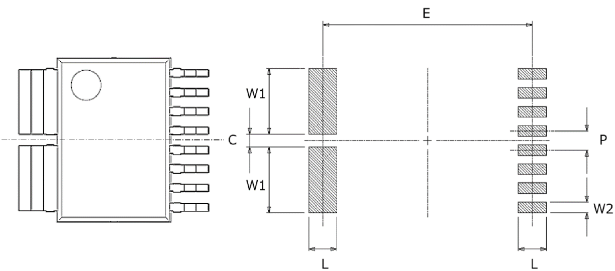
Figure 8. Recommended pad pattern 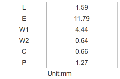
Table 5. Recommended pad dimensions Was it helpful?YesNoThank you We will reflect your opinion on the improvement of the web content.
-
[Q0362]
・Are there any other board layout guidelines of CZ-37xx?
-
A.
・Please see the application notes (2. Board Design Guidelines) here.
Was it helpful?YesNoThank you We will reflect your opinion on the improvement of the web content.
-
[Q0363]
・Is gerber file of the evaluation board provided?
-
A.
・Yes, please download from: Gerber Files.
Was it helpful?YesNoThank you We will reflect your opinion on the improvement of the web content.
-
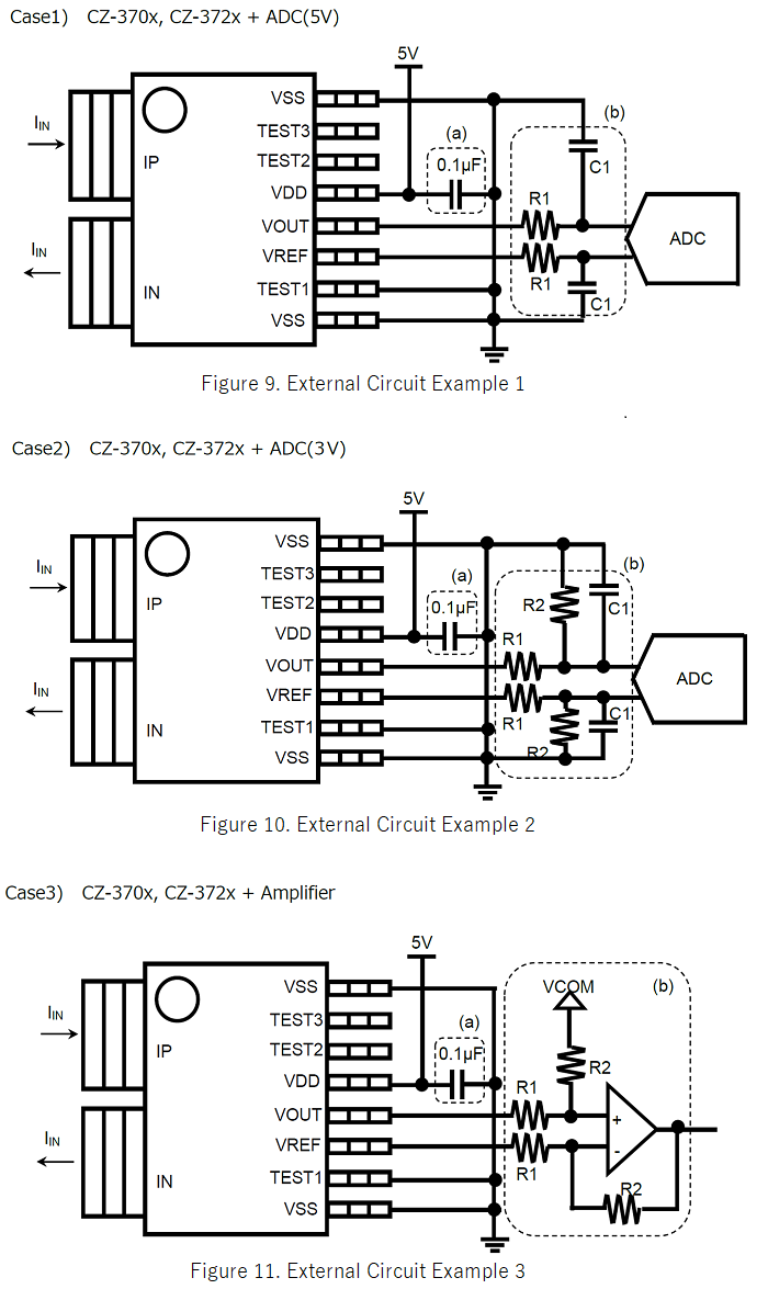
[Q0364]
・What is the recommended circuit diagram to use the CZ-370x, CZ-372x?
-
A.
・In this subsection, we show three examples of the external circuit when using CZ-370x, CZ-372x.
These are just examples and there are other possible circuits. Please evaluate your external circuit by yourself.

Case 1) Connecting a 5V A/D converter in the subsequent stage
(a) A 0.1μF bypass capacitor should be placed close to VDD and VSS pins of CZ-370x, CZ-372x.
(b) Add a low-pass filter to VOUT and VREF pins if it is necessary. The R1 and C1 values should be fixed in consideration of the time constant of the filter and load conditions.

Case 2) Connecting a 3V A/D converter in the subsequent stage
(a) 0.1μF bypass capacitor should be placed close to VDD and VSS pins of CZ-370x, CZ-372x.
(b) Add a low-pass filter to VOUT and VREF pins if it is necessary. The R1, R2 and C1 values should be fixed in consideration of the time constant and the resistive divider ratio.

Case 3) Connecting an amplifier to change the reference voltage
(a) 0.1μF bypass capacitor should be placed close to VDD and VSS pins of CZ-370x, CZ-372x.
(b) R1 and R2 are resistors that decides the gain. The R1 and R2 values should be fixed in consideration of the gain.
 Was it helpful?YesNoThank you We will reflect your opinion on the improvement of the web content.
-
[Q0365]
・I'm worried about the heat generated when applying a large current.
-
A.
・The CZ-370x, CZ-372x is capable of 60Arms continuous current, even larger current in case of transitional.
When CZ-37xx is used under conditions compliant with UL61800-5-1, please ensure the case temperature (Tc) is kept lower than 130℃ from heating by the primary current.
Please refer to the Figure 12. for the position to measure Tc.

If the heat dissipation is not enough, using thermal vias may help.
These can increase heat dissipation without increasing the trace area by thermally connecting the primary conductors to an inner or outer thermal layer directly.
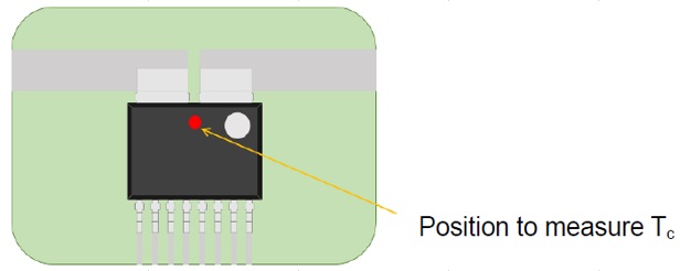
Figure 12. Position to measure package case temperature Was it helpful?YesNoThank you We will reflect your opinion on the improvement of the web content.
-
[Q0366]
・What is the ESD tolerance?
-
A.
・CZ-37xx have the ESD tolerance which is more than 2000V by human body model (HBM) and more than 200V by machine model (MM).
Was it helpful?YesNoThank you We will reflect your opinion on the improvement of the web content.
-
[Q0367]
・How much does CZ-370x, CZ-372x have influenced from the other current line?
-
A.
・There are two Hall elements inside CZ-370x, CZ-372x connected in a differential manner.
By detecting the difference of these two Hall elements’ outputs, CZ-370x, CZ-372x reduces the effects of stray magnetic fields as a built-in common-mode rejection function.
When the same magnetic field is applied to both Hall elements, this magnetic field is deemed to be the stray and is reduced from the output of CZ-370x, CZ-372x by the ratio of Stray Magnetic Field Reduction (Ebc: 0.01A/mT Typ.).

Example: When a stray magnetic field of 1mT is applied to the CZ-370x, the output will have additional error of 0.01A=10mA equivalent.
CZ-3700: Sensitivity=400mV/A, Error=10mA → Output error=4mV
CZ-3706: Sensitivity=12mV/A, Error=10mA → Output error=0.12mV

On the other hand, when different magnetic fields are applied to each Hall element, this will appear as output error.
For example, a current carrying trace that runs close the CZ-370x, CZ-372x may cause this. The extent of the error will depend on the layout of the current trace, actual current, distance from the CZ-370x, CZ-372x, and the part number (sensitivity). Figure 14 shows some simulated examples of output error by the nearby current.
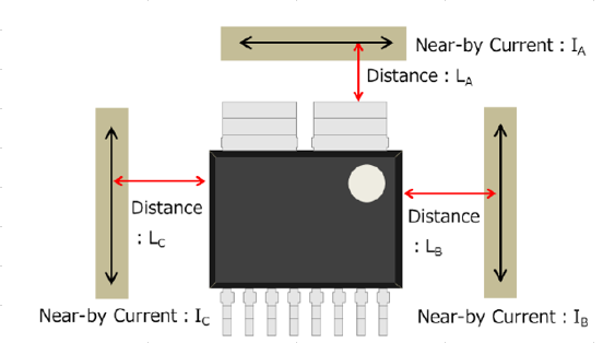
Figure 13. Examples of nearby current lines 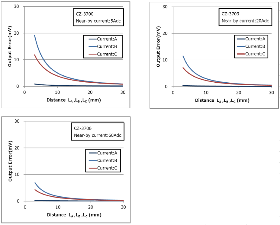
Figure 14. Output Error by nearby current Was it helpful?YesNoThank you We will reflect your opinion on the improvement of the web content.
-
[Q0368]
・Is there a way to estimate the temperature of CZ-370x, CZ-372x?
-
A.
・The temperature of the lead frame and the sensor inside the package are almost the same, the best estimated temperature would be of the lead frame.
Was it helpful?YesNoThank you We will reflect your opinion on the improvement of the web content.
-
[Q0369]
・What is the effect on the device characteristics with respect to temperature change?
-
A.
・The graphs below show the change in characteristics when the ambient temperature is changed from 25 to -40 ° C and 105 ° C.
Figure 15 shows temperature drift of sensitivity, Figure 16 shows temperature drift of zero-current output, and Figure 17 shows total accuracy.
All graphs show “Average” and “Average ±3σ” of the actual result in a certain lot.
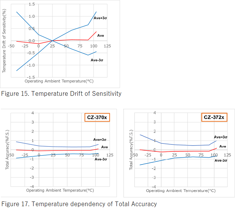
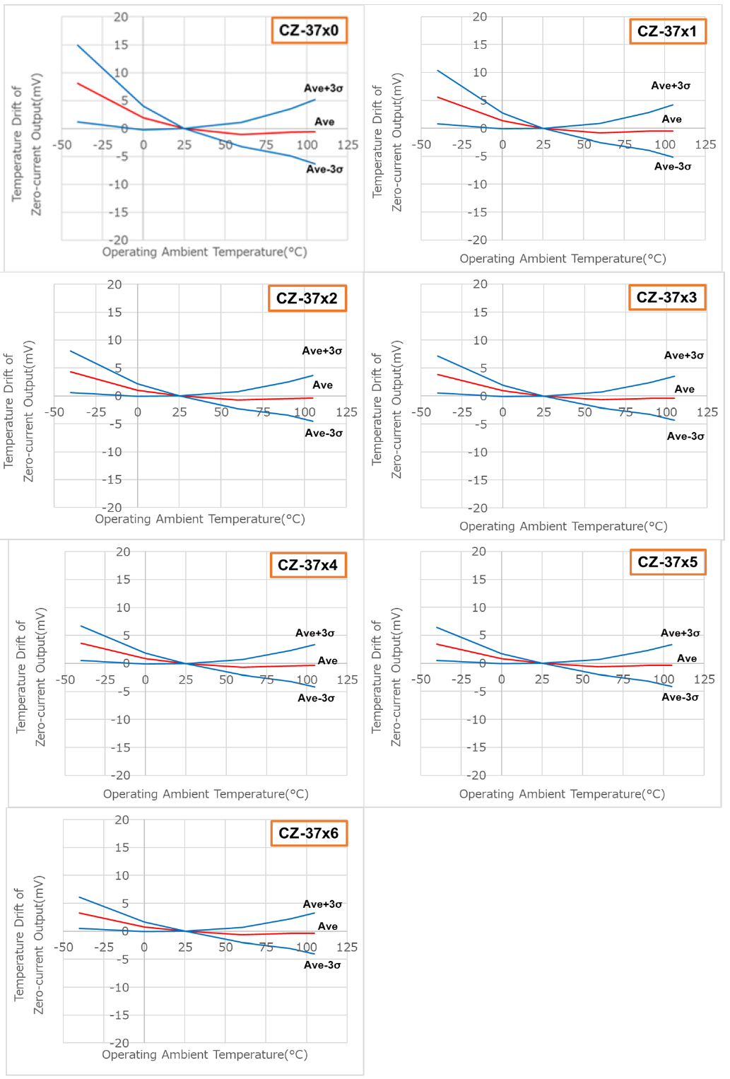
Figure 16. Temperature Drift of Zero-current Output Was it helpful?YesNoThank you We will reflect your opinion on the improvement of the web content.
-
[Q0370]
・What is the impact on output when the voltage or the current applied to the primary?
-
A.
・Figure 18. shows the dV/dt noise of CZ-370x, CZ-372x output voltage (VOUT -VREF), when 1kV is applied to the primary conductor at the rise time of 1μs.
The yellow line shows the input voltage waveform and the pink line shows the output voltage waveform.
The convergence time is as short as 2μs. It is easy to avoid this noise by adjusting the capture timing.

Figure 19. shows the output voltage (VOUT -VREF) of CZ-370x, CZ-372x, when a 25A pulse is applied to the primary conductor with a pulse width of 1μs.
The yellow line shows the input current waveform and the green line shows the output voltage waveform.
The convergence time is as short as 2μs. It is easy to avoid this noise by adjusting the capture timing.
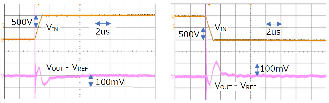
Figure 18. dV/dt noise waveform 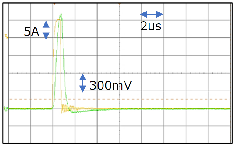
Figure 19. dI/dt noise waveform Was it helpful?YesNoThank you We will reflect your opinion on the improvement of the web content.
-
[Q0371]
・Are CZ-370x, CZ-372x halogen-free/RoHS?
-
A.
・CZ-370x, CZ-372x are halogen-free/RoHS.
Was it helpful?YesNoThank you We will reflect your opinion on the improvement of the web content.
-
[Q0372]
・Are CZ-370x, CZ-372x Pb-free?
-
A.
・CZ-370x, CZ-372x are Pb-free.
Was it helpful?YesNoThank you We will reflect your opinion on the improvement of the web content.
-
[Q0373]
・What is the primary conductor made from?
-
A.
・The primary conductor is made from copper.
Was it helpful?YesNoThank you We will reflect your opinion on the improvement of the web content.
-
[Q0374]
・What is the thermal resistance of the package?
-
A.
・The thermal resistance (θja) of CZ-370x, CZ-372x is 32°C/W when using the board shown in Figure 20.
Table 6. Thermal Resistance measurement board 
Figure 20. Thermal Resistance measurement board Was it helpful?YesNoThank you We will reflect your opinion on the improvement of the web content.
-
[Q0375]
・Is it possible to use the internal EEPROM?
-
A.
・Sorry, internal EEPROM is not available.
Products will be shipped after the adjustment of EEPROM at factory test.
Was it helpful?YesNoThank you We will reflect your opinion on the improvement of the web content.
-
[Q0376]
・Is it possible to order the customized products?
-
A.
・It is possible to customize depending on quantity conditions and requirement.
Was it helpful?YesNoThank you We will reflect your opinion on the improvement of the web content.
-
[Q0377]
・Are there any precautions when using this product for the first time?
-
A.
・The Zero-Current Output of the CZ-370x, CZ-372x may drift over time within the values defined in datasheet Section 14.
Therefore, in order to minimize this drift, we recommend calibrating the Zero-Current Output by software after the power-up time of the system when the measured current is zero.
Was it helpful?YesNoThank you We will reflect your opinion on the improvement of the web content.
-
[Q0378]
・Are there any precautions when using current sensors within the vacinity of stray magnetic fields/parts?
-
A.
・The CZ-370x, CZ-372x output can be affected by magnetic devices (mechanical relays, transformers, etc.) that are nearby.
In the case where magnetic devices must be placed close to the CZ-370x, CZ-372x, please check the effect on sensitivity or other characteristics and make sure any effects are understood and mitigated as much as possible.
Was it helpful?YesNoThank you We will reflect your opinion on the improvement of the web content.